Pull remaining cable and wire into the vehicle. Place the cable entry plate over the hole and cables. Screw in place and seal plate and screws with the approved sealant. Depending on the length of the coax and wiring on the roof, it may be necessary to secure them with cable clamps. Clamping the cable every 12" to 16" should eliminate any unecessary cable movement.
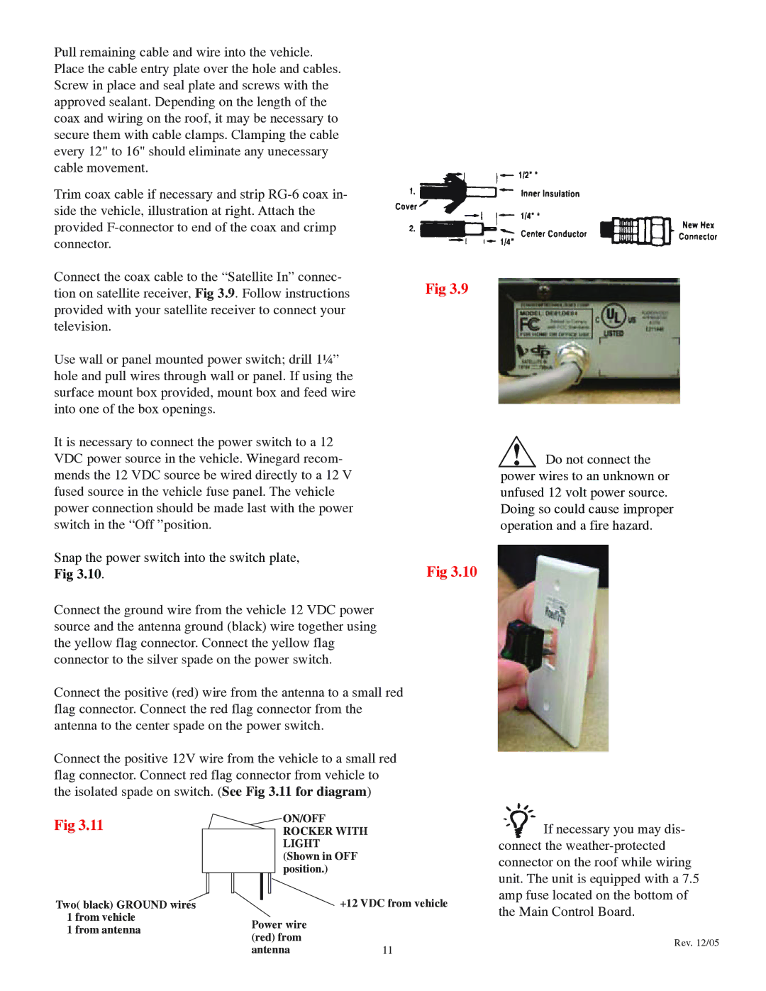
Trim coax cable if necessary and strip
Connect the coax cable to the “Satellite In” connec- | Fig 3.9 |
tion on satellite receiver, Fig 3.9. Follow instructions | |
provided with your satellite receiver to connect your |
|
television. |
|
Use wall or panel mounted power switch; drill 1¼” |
|
hole and pull wires through wall or panel. If using the |
|
surface mount box provided, mount box and feed wire |
|
into one of the box openings. |
|
It is necessary to connect the power switch to a 12 |
|
VDC power source in the vehicle. Winegard recom- |
|
mends the 12 VDC source be wired directly to a 12 V |
|
fused source in the vehicle fuse panel. The vehicle |
|
power connection should be made last with the power |
|
switch in the “Off ”position. |
|
Snap the power switch into the switch plate, | Fig 3.10 |
Fig 3.10. | |
Connect the ground wire from the vehicle 12 VDC power |
|
source and the antenna ground (black) wire together using |
|
the yellow flag connector. Connect the yellow flag |
|
connector to the silver spade on the power switch. |
|
Connect the positive (red) wire from the antenna to a small red |
|
flag connector. Connect the red flag connector from the |
|
antenna to the center spade on the power switch. |
|
Connect the positive 12V wire from the vehicle to a small red |
|
flag connector. Connect red flag connector from vehicle to |
|
the isolated spade on switch. (See Fig 3.11 for diagram) |
|
![]() Do not connect the power wires to an unknown or unfused 12 volt power source. Doing so could cause improper operation and a fire hazard.
Do not connect the power wires to an unknown or unfused 12 volt power source. Doing so could cause improper operation and a fire hazard.
Fig 3.11
Two( black) GROUND wires 1 from vehicle
1 from antenna
ON/OFF |
ROCKER WITH |
LIGHT |
(Shown in OFF |
position.) |
+12 VDC from vehicle
Power wire (red) from
antenna11
![]() If necessary you may dis- connect the
If necessary you may dis- connect the
Rev. 12/05