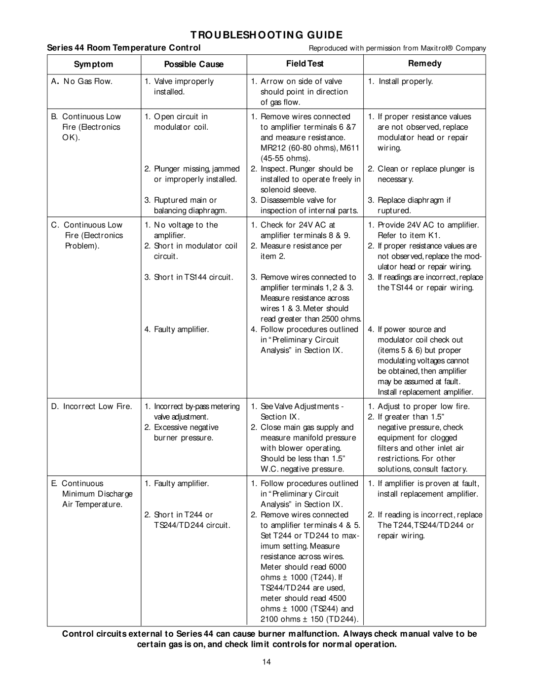
TROUBLESHOOTING GUIDE
Series 44 Room Temperature Control |
| Reproduced with permission from Maxitrol® Company | |||||
Symptom |
|
| Possible Cause |
| Field Test |
| Remedy |
|
|
|
|
|
|
|
|
A. No Gas Flow. |
|
|
| 1. | Arrow on side of valve | 1. | Install properly. |
1. | Valve improperly | ||||||
|
|
| installed. |
| should point in direction |
|
|
|
|
|
|
| of gas flow. |
|
|
|
|
|
|
|
|
|
|
B. Continuous Low |
| 1. | Open circuit in | 1. | Remove wires connected | 1. | If proper resistance values |
Fire (Electronics |
|
| modulator coil. |
| to amplifier terminals 6 &7 |
| are not observed, replace |
OK). |
|
|
|
| and measure resistance. |
| modulator head or repair |
|
|
|
|
| MR212 |
| wiring. |
|
|
|
|
|
|
| |
|
| 2. | Plunger missing, jammed | 2. | Inspect. Plunger should be | 2. | Clean or replace plunger is |
|
|
| or improperly installed. |
| installed to operate freely in |
| necessary. |
|
|
|
|
| solenoid sleeve. |
|
|
|
| 3. | Ruptured main or | 3. | Disassemble valve for | 3. | Replace diaphragm if |
|
|
| balancing diaphragm. |
| inspection of internal parts. |
| ruptured. |
|
|
|
|
|
|
|
|
C. Continuous Low |
| 1. | No voltage to the | 1. | Check for 24V AC at | 1. | Provide 24V AC to amplifier. |
Fire (Electronics |
|
| amplifier. |
| amplifier terminals 8 & 9. |
| Refer to item K1. |
Problem). |
| 2. | Short in modulator coil | 2. | Measure resistance per | 2. | If proper resistance values are |
|
|
| circuit. |
| item 2. |
| not observed, replace the mod- |
|
|
|
|
|
|
| ulator head or repair wiring. |
|
| 3. | Short in TS144 circuit. | 3. | Remove wires connected to | 3. If readings are incorrect, replace | |
|
|
|
|
| amplifier terminals 1, 2 & 3. |
| the TS144 or repair wiring. |
|
|
|
|
| Measure resistance across |
|
|
|
|
|
|
| wires 1 & 3. Meter should |
|
|
|
|
|
|
| read greater than 2500 ohms. |
|
|
|
| 4. | Faulty amplifier. | 4. | Follow procedures outlined | 4. | If power source and |
|
|
|
|
| in “Preliminary Circuit |
| modulator coil check out |
|
|
|
|
| Analysis” in Section IX. |
| (items 5 & 6) but proper |
|
|
|
|
|
|
| modulating voltages cannot |
|
|
|
|
|
|
| be obtained, then amplifier |
|
|
|
|
|
|
| may be assumed at fault. |
|
|
|
|
|
|
| Install replacement amplifier. |
|
|
|
|
|
|
|
|
D. Incorrect Low Fire. |
| 1. | Incorrect | 1. | See Valve Adjustments - | 1. | Adjust to proper low fire. |
|
|
| valve adjustment. |
| Section IX. | 2. | If greater than 1.5” |
|
| 2. | Excessive negative | 2. | Close main gas supply and |
| negative pressure, check |
|
|
| burner pressure. |
| measure manifold pressure |
| equipment for clogged |
|
|
|
|
| with blower operating. |
| filters and other inlet air |
|
|
|
|
| Should be less than 1.5” |
| restrictions. For other |
|
|
|
|
| W.C. negative pressure. |
| solutions, consult factory. |
|
|
|
|
|
|
|
|
E. Continuous |
| 1. | Faulty amplifier. | 1. | Follow procedures outlined | 1. | If amplifier is proven at fault, |
Minimum Discharge |
|
|
|
| in “Preliminary Circuit |
| install replacement amplifier. |
Air Temperature. |
|
|
|
| Analysis” in Section IX. |
|
|
|
| 2. | Short in T244 or | 2. | Remove wires connected | 2. | If reading is incorrect, replace |
|
|
| TS244/TD244 circuit. |
| to amplifier terminals 4 & 5. |
| The T244,TS244/TD244 or |
|
|
|
|
| Set T244 or TD244 to max- |
| repair wiring. |
|
|
|
|
| imum setting. Measure |
|
|
|
|
|
|
| resistance across wires. |
|
|
|
|
|
|
| Meter should read 6000 |
|
|
|
|
|
|
| ohms ± 1000 (T244). If |
|
|
|
|
|
|
| TS244/TD244 are used, |
|
|
|
|
|
|
| meter should read 4500 |
|
|
|
|
|
|
| ohms ± 1000 (TS244) and |
|
|
|
|
|
|
|
|
| |
|
|
|
|
| 2100 ohms ± 150 (TD244). |
|
|
|
|
|
|
|
|
|
|
Control circuits external to Series 44 can cause burner malfunction. Always check manual valve to be certain gas is on, and check limit controls for normal operation.
14