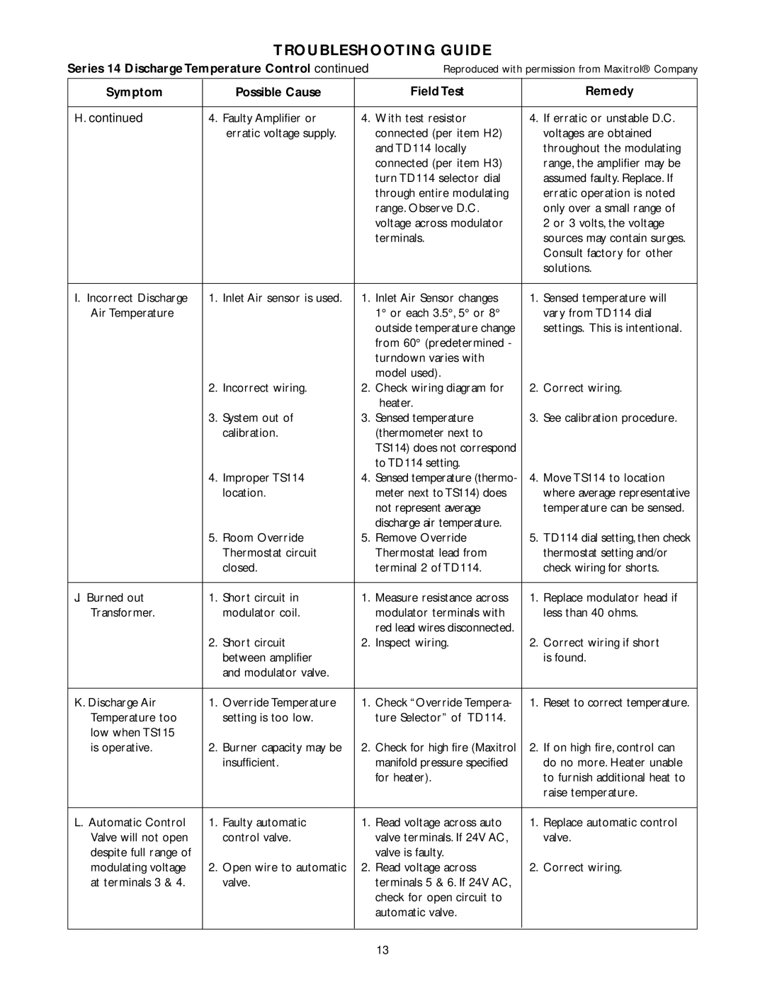
TROUBLESHOOTING GUIDE
Series 14 Discharge Temperature Control continued |
| Reproduced with permission from Maxitrol® Company | ||||||
Symptom |
|
| Possible Cause |
|
| Field Test |
| Remedy |
|
|
|
|
|
|
|
|
|
H. continued |
|
|
|
| 4. | With test resistor | 4. | If erratic or unstable D.C. |
4. | Faulty Amplifier or | |||||||
|
|
| erratic voltage supply. |
|
| connected (per item H2) |
| voltages are obtained |
|
|
|
|
|
| and TD114 locally |
| throughout the modulating |
|
|
|
|
|
| connected (per item H3) |
| range, the amplifier may be |
|
|
|
|
|
| turn TD114 selector dial |
| assumed faulty. Replace. If |
|
|
|
|
|
| through entire modulating |
| erratic operation is noted |
|
|
|
|
|
| range. Observe D.C. |
| only over a small range of |
|
|
|
|
|
| voltage across modulator |
| 2 or 3 volts, the voltage |
|
|
|
|
|
| terminals. |
| sources may contain surges. |
|
|
|
|
|
|
|
| Consult factory for other |
|
|
|
|
|
|
|
| solutions. |
|
|
|
|
|
|
|
|
|
I. Incorrect Discharge |
| 1. | Inlet Air sensor is used. |
| 1. | Inlet Air Sensor changes | 1. | Sensed temperature will |
Air Temperature |
|
|
|
|
| 1° or each 3.5°, 5° or 8° |
| vary from TD114 dial |
|
|
|
|
|
| outside temperature change |
| settings. This is intentional. |
|
|
|
|
|
| from 60° (predetermined - |
|
|
|
|
|
|
|
| turndown varies with |
|
|
|
|
|
|
|
| model used). |
|
|
|
| 2. | Incorrect wiring. |
| 2. | Check wiring diagram for | 2. | Correct wiring. |
|
|
|
|
|
| heater. |
|
|
|
| 3. | System out of |
| 3. | Sensed temperature | 3. | See calibration procedure. |
|
|
| calibration. |
|
| (thermometer next to |
|
|
|
|
|
|
|
| TS114) does not correspond |
|
|
|
|
|
|
|
| to TD114 setting. |
|
|
|
| 4. | Improper TS114 |
| 4. | Sensed temperature (thermo- | 4. | Move TS114 to location |
|
|
| location. |
|
| meter next to TS114) does |
| where average representative |
|
|
|
|
|
| not represent average |
| temperature can be sensed. |
|
|
|
|
|
| discharge air temperature. |
|
|
|
| 5. | Room Override |
| 5. | Remove Override | 5. | TD114 dial setting, then check |
|
|
| Thermostat circuit |
|
| Thermostat lead from |
| thermostat setting and/or |
|
|
| closed. |
|
| terminal 2 of TD114. |
| check wiring for shorts. |
|
|
|
|
|
|
|
|
|
J. Burned out |
| 1. | Short circuit in |
| 1. | Measure resistance across | 1. | Replace modulator head if |
Transformer. |
|
| modulator coil. |
|
| modulator terminals with |
| less than 40 ohms. |
|
|
|
|
|
| red lead wires disconnected. |
|
|
|
| 2. | Short circuit |
| 2. | Inspect wiring. | 2. | Correct wiring if short |
|
|
| between amplifier |
|
|
|
| is found. |
|
|
| and modulator valve. |
|
|
|
|
|
|
|
|
|
|
|
|
|
|
K. Discharge Air |
| 1. | Override Temperature |
| 1. | Check “Override Tempera- | 1. | Reset to correct temperature. |
Temperature too |
|
| setting is too low. |
|
| ture Selector” of TD114. |
|
|
low when TS115 |
|
|
|
|
|
|
|
|
is operative. |
| 2. | Burner capacity may be |
| 2. | Check for high fire (Maxitrol | 2. | If on high fire, control can |
|
|
| insufficient. |
|
| manifold pressure specified |
| do no more. Heater unable |
|
|
|
|
|
| for heater). |
| to furnish additional heat to |
|
|
|
|
|
|
|
| raise temperature. |
|
|
|
|
|
|
|
|
|
L. Automatic Control |
| 1. | Faulty automatic |
| 1. | Read voltage across auto | 1. | Replace automatic control |
Valve will not open |
|
| control valve. |
|
| valve terminals. If 24V AC, |
| valve. |
despite full range of |
|
|
|
|
| valve is faulty. |
|
|
modulating voltage |
| 2. | Open wire to automatic |
| 2. | Read voltage across | 2. | Correct wiring. |
at terminals 3 & 4. |
|
| valve. |
|
| terminals 5 & 6. If 24V AC, |
|
|
|
|
|
|
|
| check for open circuit to |
|
|
|
|
|
|
|
| automatic valve. |
|
|
|
|
|
|
|
|
|
| |
|
|
|
|
|
|
|
|
|
13
