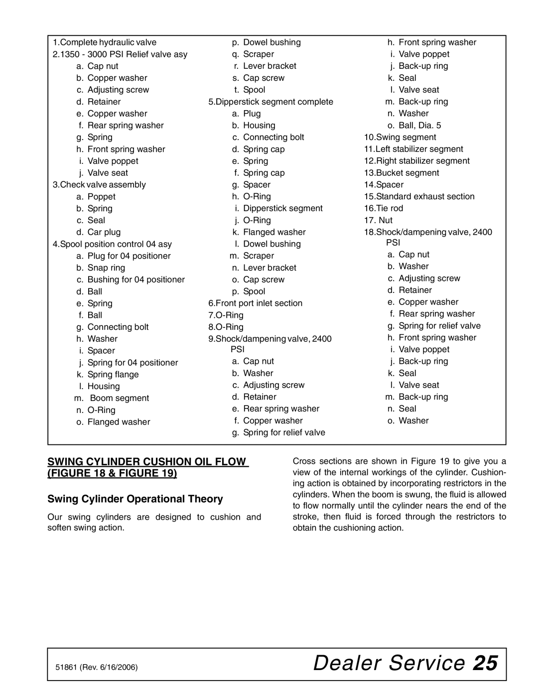
1.Complete hydraulic valve | p. Dowel bushing | h. Front spring washer |
2.1350 - 3000 PSI Relief valve asy | q. Scraper | i. Valve poppet |
a. Cap nut | r. Lever bracket | j. |
b. Copper washer | s. Cap screw | k. Seal |
c. Adjusting screw | t. Spool | l. Valve seat |
d. Retainer | 5.Dipperstick segment complete | m. |
e. Copper washer | a. Plug | n. Washer |
f. Rear spring washer | b. Housing | o. Ball, Dia. 5 |
g. Spring | c. Connecting bolt | 10.Swing segment |
h. Front spring washer | d. Spring cap | 11.Left stabilizer segment |
i. Valve poppet | e. Spring | 12.Right stabilizer segment |
j. Valve seat | f. Spring cap | 13.Bucket segment |
3.Check valve assembly | g. Spacer | 14.Spacer |
a. Poppet | h. | 15.Standard exhaust section |
b. Spring | i. Dipperstick segment | 16.Tie rod |
c. Seal | j. | 17. Nut |
d. Car plug | k. Flanged washer | 18.Shock/dampening valve, 2400 |
4.Spool position control 04 asy | l. Dowel bushing | PSI |
a. Plug for 04 positioner | m. Scraper | a. Cap nut |
b. Snap ring | n. Lever bracket | b. Washer |
c. Bushing for 04 positioner | o. Cap screw | c. Adjusting screw |
d. Ball | p. Spool | d. Retainer |
e. Spring | 6.Front port inlet section | e. Copper washer |
f. Ball | f. Rear spring washer | |
g. Connecting bolt | g. Spring for relief valve | |
h. Washer | 9.Shock/dampening valve, 2400 | h. Front spring washer |
i. Spacer | PSI | i. Valve poppet |
j. Spring for 04 positioner | a. Cap nut | j. |
k. Spring flange | b. Washer | k. Seal |
l. Housing | c. Adjusting screw | l. Valve seat |
m. Boom segment | d. Retainer | m. |
n. | e. Rear spring washer | n. Seal |
o. Flanged washer | f. Copper washer | o. Washer |
| g. Spring for relief valve |
|
|
|
|
SWING CYLINDER CUSHION OIL FLOW (FIGURE 18 & FIGURE 19)
Swing Cylinder Operational Theory
Our swing cylinders are designed to cushion and soften swing action.
Cross sections are shown in Figure 19 to give you a view of the internal workings of the cylinder. Cushion- ing action is obtained by incorporating restrictors in the cylinders. When the boom is swung, the fluid is allowed to flow normally until the cylinder nears the end of the stroke, then fluid is forced through the restrictors to obtain the cushioning action.
51861 (Rev. 6/16/2006) | Dealer Service 25 |
|
|
