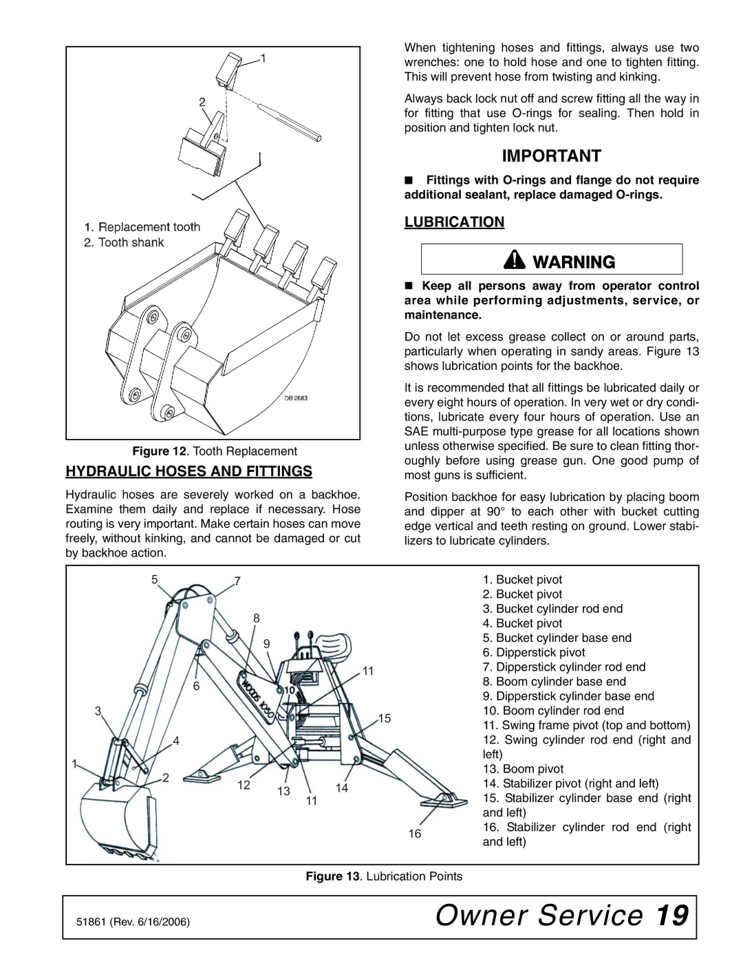
Figure 12. Tooth Replacement
HYDRAULIC HOSES AND FITTINGS
Hydraulic hoses are severely worked on a backhoe. Examine them daily and replace if necessary. Hose routing is very important. Make certain hoses can move freely, without kinking, and cannot be damaged or cut by backhoe action.
When tightening hoses and fittings, always use two wrenches: one to hold hose and one to tighten fitting. This will prevent hose from twisting and kinking.
Always back lock nut off and screw fitting all the way in for fitting that use
IMPORTANT
■ Fittings with
LUBRICATION
Keep all persons away from operator control area while performing adjustments, service, or maintenance.
Do not let excess grease collect on or around parts, particularly when operating in sandy areas. Figure 13 shows lubrication points for the backhoe.
It is recommended that all fittings be lubricated daily or every eight hours of operation. In very wet or dry condi- tions, lubricate every four hours of operation. Use an SAE
Position backhoe for easy lubrication by placing boom and dipper at 90° to each other with bucket cutting edge vertical and teeth resting on ground. Lower stabi- lizers to lubricate cylinders.
.
5 |
| 7 |
|
|
|
| 1. | Bucket pivot | |
|
|
|
|
|
|
| 2. | Bucket pivot | |
|
|
| 8 |
|
|
| 3. | Bucket cylinder rod end | |
|
|
|
|
|
| 4. | Bucket pivot | ||
|
|
|
|
|
|
| |||
|
|
| 9 |
|
|
| 5. | Bucket cylinder base end | |
|
|
|
|
|
| 6. | Dipperstick pivot | ||
|
|
|
|
|
|
| |||
|
|
|
| 11 |
|
| 7. | Dipperstick cylinder rod end | |
|
| 6 |
|
|
|
| 8. | Boom cylinder base end | |
|
|
|
|
|
| 9. | Dipperstick cylinder base end | ||
|
|
|
|
|
|
| |||
3 |
|
|
|
| 15 |
| 10. | Boom cylinder rod end | |
|
|
|
|
|
| 11. Swing frame pivot (top and bottom) | |||
|
|
|
|
|
|
| |||
|
| 4 |
|
|
|
| 12. | Swing cylinder rod end (right and | |
1 |
|
|
|
|
|
| left) |
| |
2 |
|
|
|
|
| 13. | Boom pivot | ||
|
|
|
|
|
| ||||
| 12 | 13 | 14 |
|
| 14. | Stabilizer pivot (right and left) | ||
|
|
|
| ||||||
|
|
|
| 15. | Stabilizer cylinder base end (right | ||||
|
|
|
| 11 |
|
| |||
|
|
|
|
|
|
| and left) | ||
|
|
|
|
|
| 16 | 16. | Stabilizer cylinder rod end (right | |
|
|
|
|
|
| and left) | |||
|
|
|
|
|
|
| |||
Figure 13. Lubrication Points
51861 (Rev. 6/16/2006) | Owner Service 19 |
|
|