Make sure you meet minimum clearance distances between ROPS or tractor cab. Required head clear- ance must take priority. Refer to Danger decal on page 10. Make any adjustments required.
1.The bolt center distance attaching the diagonal brace to the top link must not be more than
2.The bolts joining the two halves of the top link must not be less than
3.The vertical distance between the attachment point for the lower lift arms and the top link pin must not be less that 12".
When clearance distances are verified and attachment is complete, tighten hitch pin nuts to 600
Mount backhoe to tractor and tighten bolts attaching
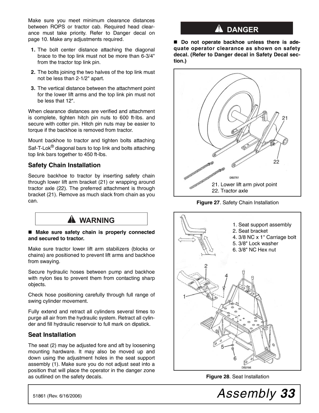
Safety Chain Installation
Secure backhoe to tractor by inserting safety chain through lower lift arm bracket (21) or wrapping around tractor axle (22). The preferred attachment is through bracket (21). Remove as much slack from chain as you can.
A WARNING
Make sure safety chain is properly connected and secured to tractor.
Make sure tractor lower lift arm stabilizers (blocks or chains) are positioned to prevent lift arms and backhoe from swaying.
Secure hydraulic hoses between pump and backhoe with nylon ties to prevent them from contacting sharp objects.
Check hose positioning carefully through full range of swing cylinder movement.
Fully extend and retract all cylinders several times to purge all air from the hydraulic system. Retract all cylin- der and fill hydraulic reservoir to full mark on dipstick.
Seat Installation
The seat (2) may be adjusted fore and aft by loosening mounting hardware. It may also be moved up and down using the adjustment holes in the seat support assembly (1). Make sure you do not adjust seat into a position that will place the operator in the danger zone as outlined on the safety decals.
A DANGER
Do not operate backhoe unless there is ade- quate operator clearance as shown on safety decal. (Refer to Danger decal in Safety Decal sec- tion.)
21.Lower lift arm pivot point
22.Tractor axle
Figure 27. Safety Chain Installation
1.Seat support assembly
2.Seat bracket
4.3/8 NC x 1" Carriage bolt
5.3/8" Lock washer
6.3/8" NC Hex nut
Figure 28. Seat Installation
51861 (Rev. 6/16/2006) | Assembly 33 |
|
|