Assembly
Lubricate
Place wiper ring (3C) in outer rod guide groove. Slide rod guide assembly (5) onto rod (1). Place wear ring (3I) in narrow groove of piston. Place piston ring (3G) in wide piston groove.
Lightly coat rod threads with hydraulic oil and slide O- ring (3A) over threads and into groove. Install piston (6) onto rod (1) with wear ring on side away from rod guide. Install lock nut (7) and torque to 175
Compress wear ring and piston seal and carefully insert piston and rod assembly into barrel. Use care to prevent damage while installing.
Carefully push or tap rod guide (5) into barrel (8) just past groove inside barrel. Insert retaining ring (3B) into groove and pull rod (1) to seat rod guide (5) against ring. Screw spanner nut (4) into rod guide (5) using a spanner wrench, or carefully use a punch and hammer.
their various positions and make certain the correct operation occurs corresponding to the decals on the operator's console. Pay specific attention to the float position of the boom. Do not operate backhoe if func- tions differ from the decal.
If the functions differ from the decal, check to make sure control linkage is correctly installed and check plumbing schematics to make sure hoses are correctly connected.
1.Piston rod | 3G. Piston ring | ||
3A. | 3I. Piston ring | ||
3B. | Retaining ring | 4. | Spanner nut |
3C. Wiper ring | 5. | Rod guide asy | |
3D. Rod seal | 6. | Piston | |
3E. | 7. | Lock nut | |
3F. | 8. | Cylinder barrel | |
Figure 15. Hydraulic Cylinder Assembly
Installing Valve
Reconnect control linkage to valve.
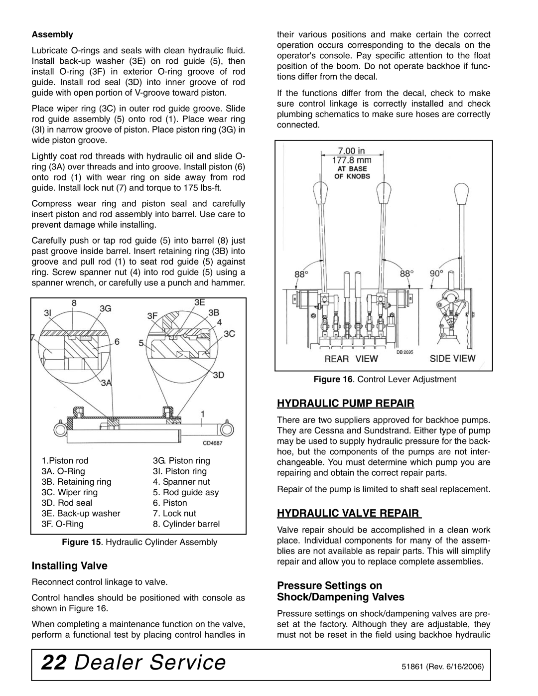
Control handles should be positioned with console as shown in Figure 16.
When completing a maintenance function on the valve, perform a functional test by placing control handles in
Figure 16. Control Lever Adjustment
HYDRAULIC PUMP REPAIR
There are two suppliers approved for backhoe pumps. They are Cessna and Sundstrand. Either type of pump may be used to supply hydraulic pressure for the back- hoe, but the components of the pumps are not inter- changeable. You must determine which pump you are repairing and obtain the correct repair parts.
Repair of the pump is limited to shaft seal replacement.
HYDRAULIC VALVE REPAIR
Valve repair should be accomplished in a clean work place. Individual components for many of the assem- blies are not available as repair parts. This will simplify repair and allow you to replace complete assemblies.
Pressure Settings on
Shock/Dampening Valves
Pressure settings on shock/dampening valves are pre- set at the factory. Although they are adjustable, they must not be reset in the field using backhoe hydraulic
22 Dealer Service | 51861 (Rev. 6/16/2006) |
|
|