BLADE SERVICE
Blade Removal
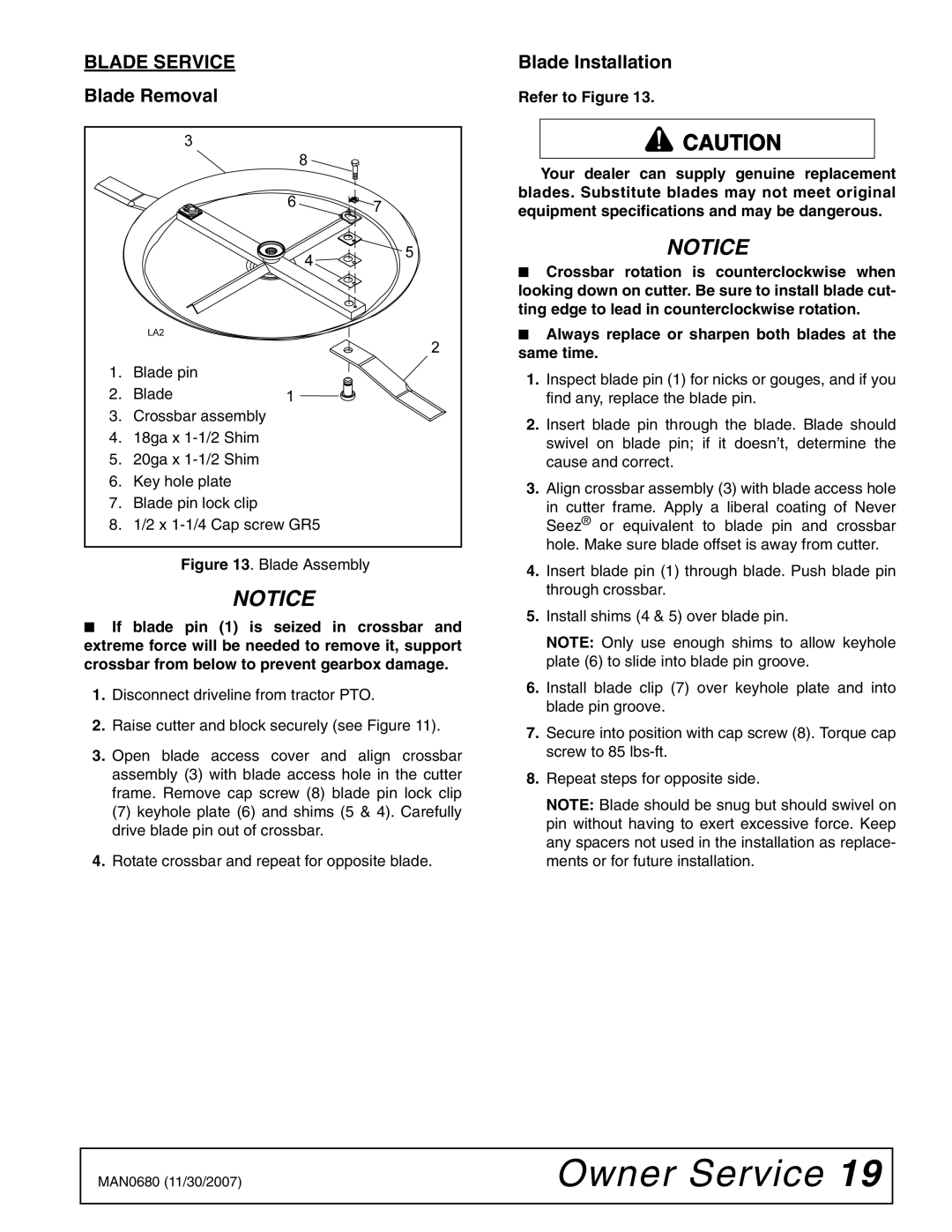
1.Blade pin
2.Blade
3.Crossbar assembly
4.18ga x
5.20ga x
6.Key hole plate
7.Blade pin lock clip
8.1/2 x
Figure 13. Blade Assembly
NOTICE
■If blade pin (1) is seized in crossbar and extreme force will be needed to remove it, support crossbar from below to prevent gearbox damage.
1.Disconnect driveline from tractor PTO.
2.Raise cutter and block securely (see Figure 11).
3.Open blade access cover and align crossbar assembly (3) with blade access hole in the cutter frame. Remove cap screw (8) blade pin lock clip
(7)keyhole plate (6) and shims (5 & 4). Carefully drive blade pin out of crossbar.
4.Rotate crossbar and repeat for opposite blade.
Blade Installation
Refer to Figure 13.
![]() CAUTION
CAUTION
Your dealer can supply genuine replacement blades. Substitute blades may not meet original equipment specifications and may be dangerous.
NOTICE
■Crossbar rotation is counterclockwise when looking down on cutter. Be sure to install blade cut- ting edge to lead in counterclockwise rotation.
■Always replace or sharpen both blades at the same time.
1.Inspect blade pin (1) for nicks or gouges, and if you find any, replace the blade pin.
2.Insert blade pin through the blade. Blade should swivel on blade pin; if it doesn’t, determine the cause and correct.
3.Align crossbar assembly (3) with blade access hole
in cutter frame. Apply a liberal coating of Never Seez® or equivalent to blade pin and crossbar hole. Make sure blade offset is away from cutter.
4.Insert blade pin (1) through blade. Push blade pin through crossbar.
5.Install shims (4 & 5) over blade pin.
NOTE: Only use enough shims to allow keyhole plate (6) to slide into blade pin groove.
6.Install blade clip (7) over keyhole plate and into blade pin groove.
7.Secure into position with cap screw (8). Torque cap screw to 85
8.Repeat steps for opposite side.
NOTE: Blade should be snug but should swivel on pin without having to exert excessive force. Keep any spacers not used in the installation as replace- ments or for future installation.
MAN0680 (11/30/2007) | Owner Service 19 |
|
|