BAFFLE KIT INSTALLATION (OPTIONAL)
NOTE: An optional baffle kit may be installed to the front of the cutter to prevent excessive
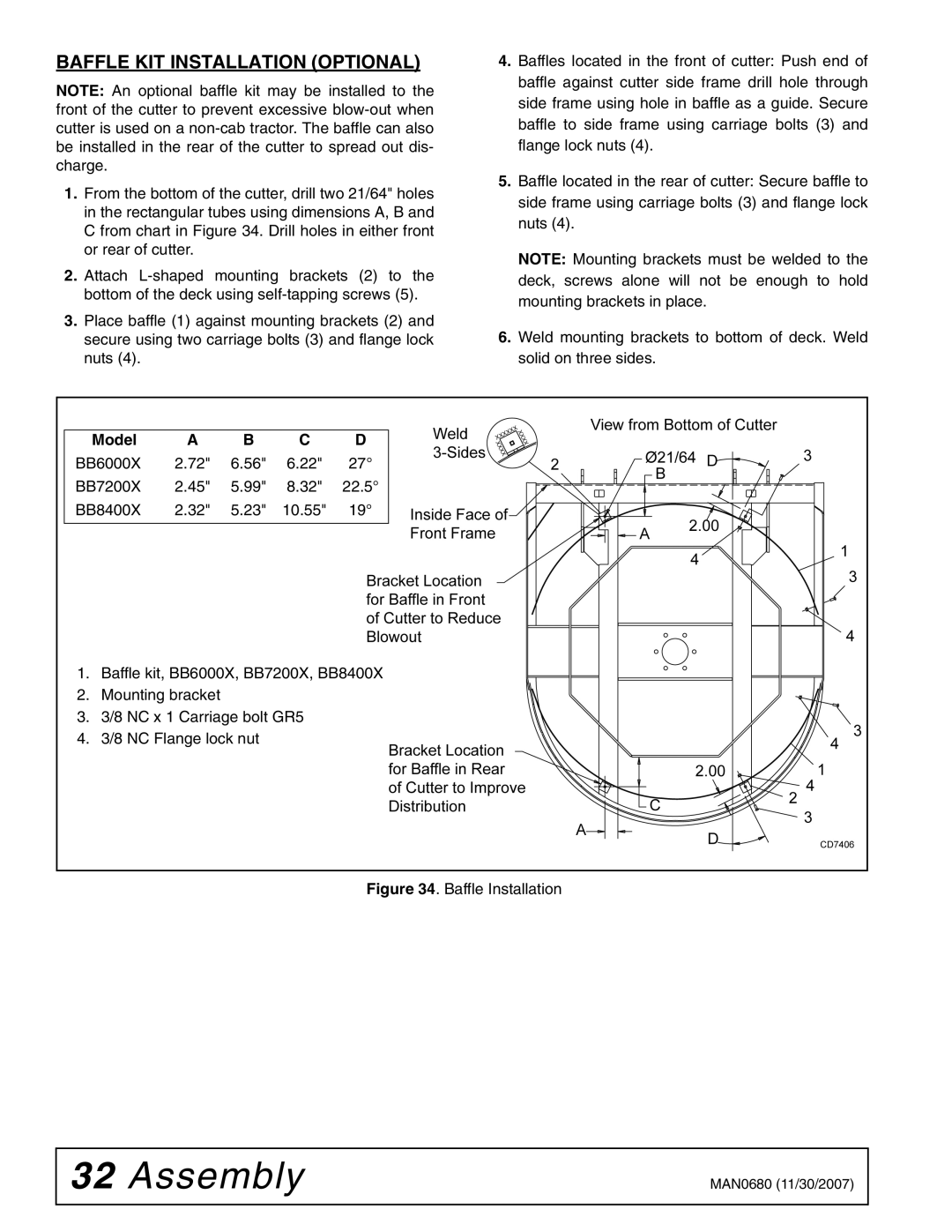
1.From the bottom of the cutter, drill two 21/64" holes in the rectangular tubes using dimensions A, B and C from chart in Figure 34. Drill holes in either front or rear of cutter.
2.Attach
3.Place baffle (1) against mounting brackets (2) and secure using two carriage bolts (3) and flange lock nuts (4).
4.Baffles located in the front of cutter: Push end of baffle against cutter side frame drill hole through side frame using hole in baffle as a guide. Secure baffle to side frame using carriage bolts (3) and flange lock nuts (4).
5.Baffle located in the rear of cutter: Secure baffle to side frame using carriage bolts (3) and flange lock nuts (4).
NOTE: Mounting brackets must be welded to the deck, screws alone will not be enough to hold mounting brackets in place.
6.Weld mounting brackets to bottom of deck. Weld solid on three sides.
Model | A | B | C | D |
BB6000X 2.72" 6.56" 6.22" 27°
BB7200X 2.45" 5.99" 8.32" 22.5°
BB8400X 2.32" 5.23" 10.55" 19°
1.Baffle kit, BB6000X, BB7200X, BB8400X
2.Mounting bracket
3.3/8 NC x 1 Carriage bolt GR5
4.3/8 NC Flange lock nut
Figure 34. Baffle Installation
32 Assembly | MAN0680 (11/30/2007) |
|
|