Disassemble Shipping Unit
Refer to Figure 29.
1.Position cutter flat and place a block underneath the rear of the cutter to raise it off the ground.
2.Remove all parts that are wired or strapped to cutter. Remove parts from manual tube and hardware that is securing tailwheel bracket (3) and brace arms (8) to cutter.
ASSEMBLE CUTTER
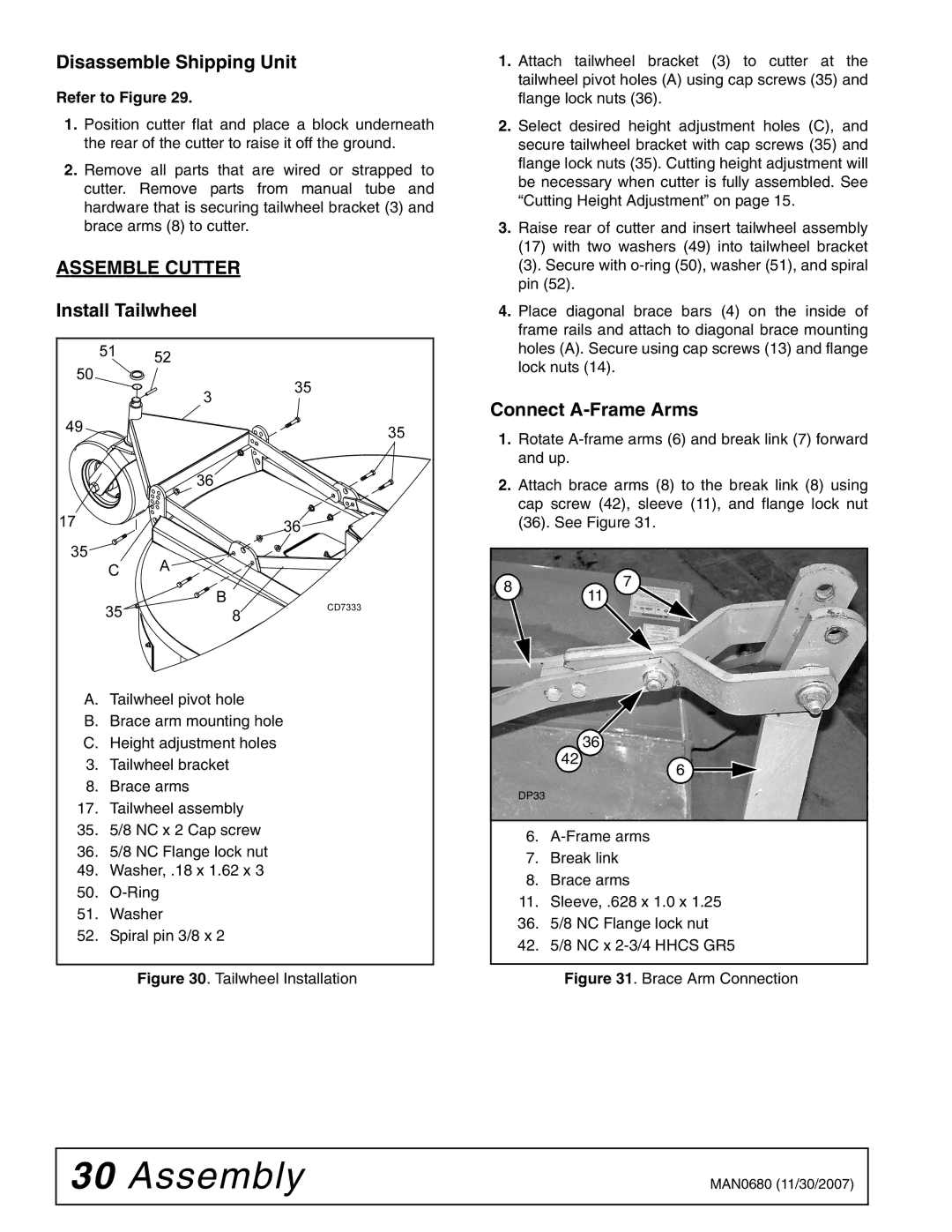
Install Tailwheel
A.Tailwheel pivot hole
B.Brace arm mounting hole
C.Height adjustment holes
3.Tailwheel bracket
8.Brace arms
17.Tailwheel assembly
35.5/8 NC x 2 Cap screw
36.5/8 NC Flange lock nut
49.Washer, .18 x 1.62 x 3
50.
51.Washer
52.Spiral pin 3/8 x 2
Figure 30. Tailwheel Installation
1.Attach tailwheel bracket (3) to cutter at the tailwheel pivot holes (A) using cap screws (35) and flange lock nuts (36).
2.Select desired height adjustment holes (C), and secure tailwheel bracket with cap screws (35) and flange lock nuts (35). Cutting height adjustment will be necessary when cutter is fully assembled. See “Cutting Height Adjustment” on page 15.
3.Raise rear of cutter and insert tailwheel assembly
(17)with two washers (49) into tailwheel bracket
(3). Secure with o-ring (50), washer (51), and spiral pin (52).
4.Place diagonal brace bars (4) on the inside of frame rails and attach to diagonal brace mounting holes (A). Secure using cap screws (13) and flange lock nuts (14).
Connect A-Frame Arms
1.Rotate
2.Attach brace arms (8) to the break link (8) using cap screw (42), sleeve (11), and flange lock nut (36). See Figure 31.
8 | 7 | |
11 | ||
|
36
42
6 |
DP33
6.
7.Break link
8.Brace arms
11. Sleeve, .628 x 1.0 x 1.25
36. 5/8 NC Flange lock nut
42. 5/8 NC x
Figure 31. Brace Arm Connection
30 Assembly | MAN0680 (11/30/2007) |
|
|