D. FENCE CLAMPING
PRESSURE
If you can move the locked fence by exerting approximately 50 lbs. of lateral force, the fence clamping mechanism will require adjustment. It is quicker and easier to adjust the fence while it is on the saw; however, reaching underneath the fence may be awkward for some people. Removing the fence and laying it upside down on a bench to work on is another option. With this method, you may have to slide the fence on and off several times.
Before starting, review the adjustment steps while looking at the parts breakdown near the end of this manual.
Step 1.
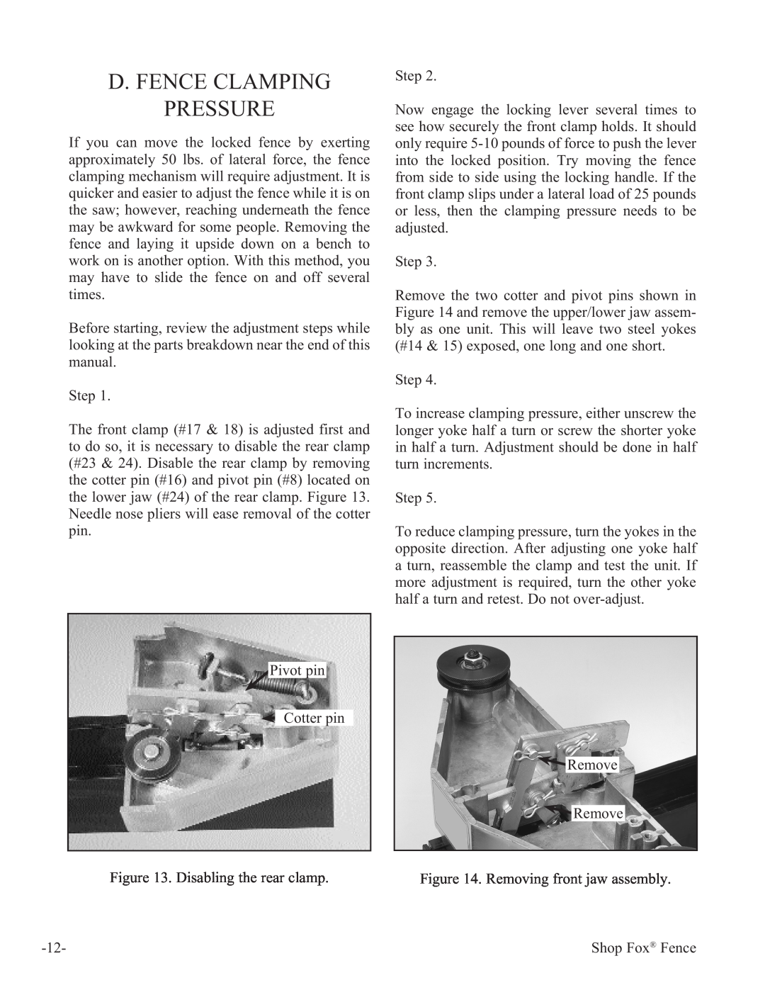
The front clamp (#17 & 18) is adjusted first and to do so, it is necessary to disable the rear clamp (#23 & 24). Disable the rear clamp by removing the cotter pin (#16) and pivot pin (#8) located on the lower jaw (#24) of the rear clamp. Figure 13. Needle nose pliers will ease removal of the cotter pin.
Pivot pin
![]() Cotter pin
Cotter pin
Step 2.
Now engage the locking lever several times to see how securely the front clamp holds. It should only require
Step 3.
Remove the two cotter and pivot pins shown in Figure 14 and remove the upper/lower jaw assem- bly as one unit. This will leave two steel yokes (#14 & 15) exposed, one long and one short.
Step 4.
To increase clamping pressure, either unscrew the longer yoke half a turn or screw the shorter yoke in half a turn. Adjustment should be done in half turn increments.
Step 5.
To reduce clamping pressure, turn the yokes in the opposite direction. After adjusting one yoke half a turn, reassemble the clamp and test the unit. If more adjustment is required, turn the other yoke half a turn and retest. Do not
![]() Remove
Remove
![]() Remove
Remove
Figure 13. Disabling the rear clamp. | Figure 14. Removing front jaw assembly. |
Shop Fox® Fence |