Model W1822 (For Machines Mfg. Since 9/10)
17. | Remove the |
|
|
|
|
|
|
|
|
|
|
|
| ||
| of the crosscut fence and set it aside for use in the |
|
| Forward |
|
|
|
| next steps. |
|
| Set Screw |
|
|
|
|
|
|
|
|
|
|
|
18. | Slide the miter gauge bar into the sliding table miter |
|
|
|
|
| |
| gauge slot, as shown in Figure 13. |
|
|
|
|
|
|
|
|
|
|
|
|
|
|
|
|
|
|
|
|
|
|
|
|
|
|
|
|
|
|
19.While holding the crosscut fence in position, rotate it slightly so that you can insert the
20.Position the fence along the table, then tighten the forward miter gauge bar set screw (see Figure 13) and the miter gauge lock knob (see Figure 14) to secure the fence in place.
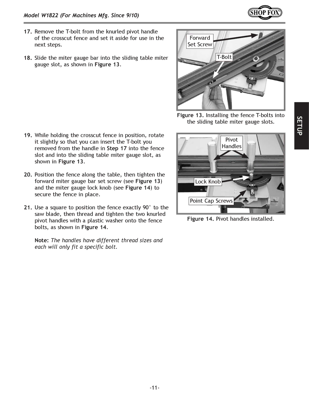
21.Use a square to position the fence exactly 90° to the saw blade, then thread and tighten the two knurled pivot handles with a plastic washer onto the fence bolts, as shown in Figure 14.
Note: The handles have different thread sizes and each will only fit a specific bolt.
Figure 13. Installing the fence T-bolts into
the sliding table miter gauge slots.
Pivot
Handles
Lock Knob
Point Cap Screws
Figure 14. Pivot handles installed.
SETUP