Auxiliary Power Connector (AUX POWER OUT) – D5RH and D5SH, D5SH4
For wire runs over 150’, it is recommended to run an additional 16
To make connections:
1Ensure that system power is OFF!
2Strip the ends of the 16 AWG wire 1/4" on both ends of the wire run.
3Remove the terminal strip from the AUX POWER OUT connector on the D5RH or D5SH, D5SH4.
4Loosen the screws for the appropriate zone’s terminal pairs on the terminal strip.
5Insert the wires into the terminal strip, paying close attention to polarity
6Tighten the screws on the terminal strip.
7Remove the terminal strip from the PWR IN connector of the D5KP.
8Loosen the screws on the D5KP’s PWR IN terminal.
9Insert the wires into the terminal, paying close attention to polarity
10Tighten the screws on the D5KP’s PWR IN terminal.
11Connect the terminal strip back onto the AUX POWER OUT connector on the D5RH or D5SH, D5SH4.
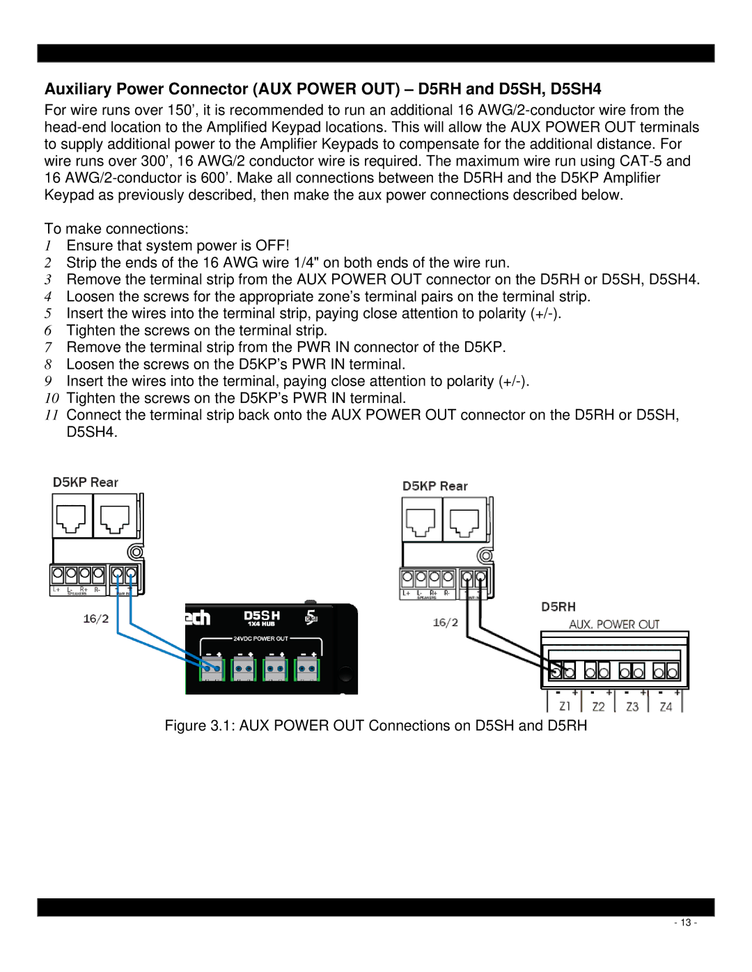
Figure 3.1: AUX POWER OUT Connections on D5SH and D5RH
- 13 -