RS2321X8 Serial RouterPage 13
APPENDIX:
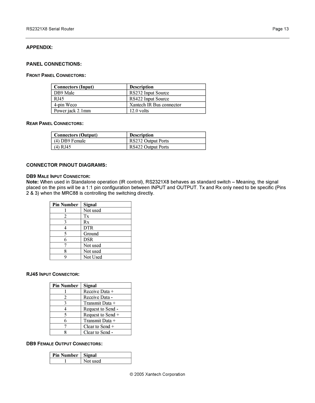
PANEL CONNECTIONS:
FRONT PANEL CONNECTORS:
| Connectors (Input) | Description | |
| DB9 Male | RS232 Input Source | |
| RJ45 | RS422 Input Source | |
| Xantech IR Bus connector | ||
| Power jack 2.1mm | 12.0 volts | |
REAR PANEL CONNECTORS: |
| ||
|
|
| |
| Connectors (Output) | Description | |
| (4) | DB9 Female | RS232 Output Ports |
| (4) | RJ45 | RS422 Output Ports |
CONNECTOR PINOUT DIAGRAMS:
DB9 MALE INPUT CONNECTOR:
Note: When used in Standalone operation (IR control), RS2321X8 behaves as standard switch – Meaning, the signal placed on the pins will be a 1:1 pin configuration between INPUT and OUTPUT. Tx and Rx only need to be specific (Pins 2 & 3) when the MRC88 is controlling the switching directly.
| Pin Number | Signal |
| 1 | Not used |
| 2 | Tx |
| 3 | Rx |
| 4 | DTR |
| 5 | Ground |
| 6 | DSR |
| 7 | Not used |
| 8 | Not used |
| 9 | Not Used |
RJ45 INPUT CONNECTOR: |
| |
|
|
|
| Pin Number | Signal |
| 1 | Receive Data + |
| 2 | Receive Data - |
| 3 | Transmit Data + |
| 4 | Request to Send - |
| 5 | Request to Send + |
| 6 | Transmit Data + |
| 7 | Clear to Send + |
| 8 | Clear to Send - |
DB9 FEMALE OUTPUT CONNECTORS: | ||
|
|
|
| Pin Number | Signal |
| 1 | Not used |
© 2005 Xantech Corporation