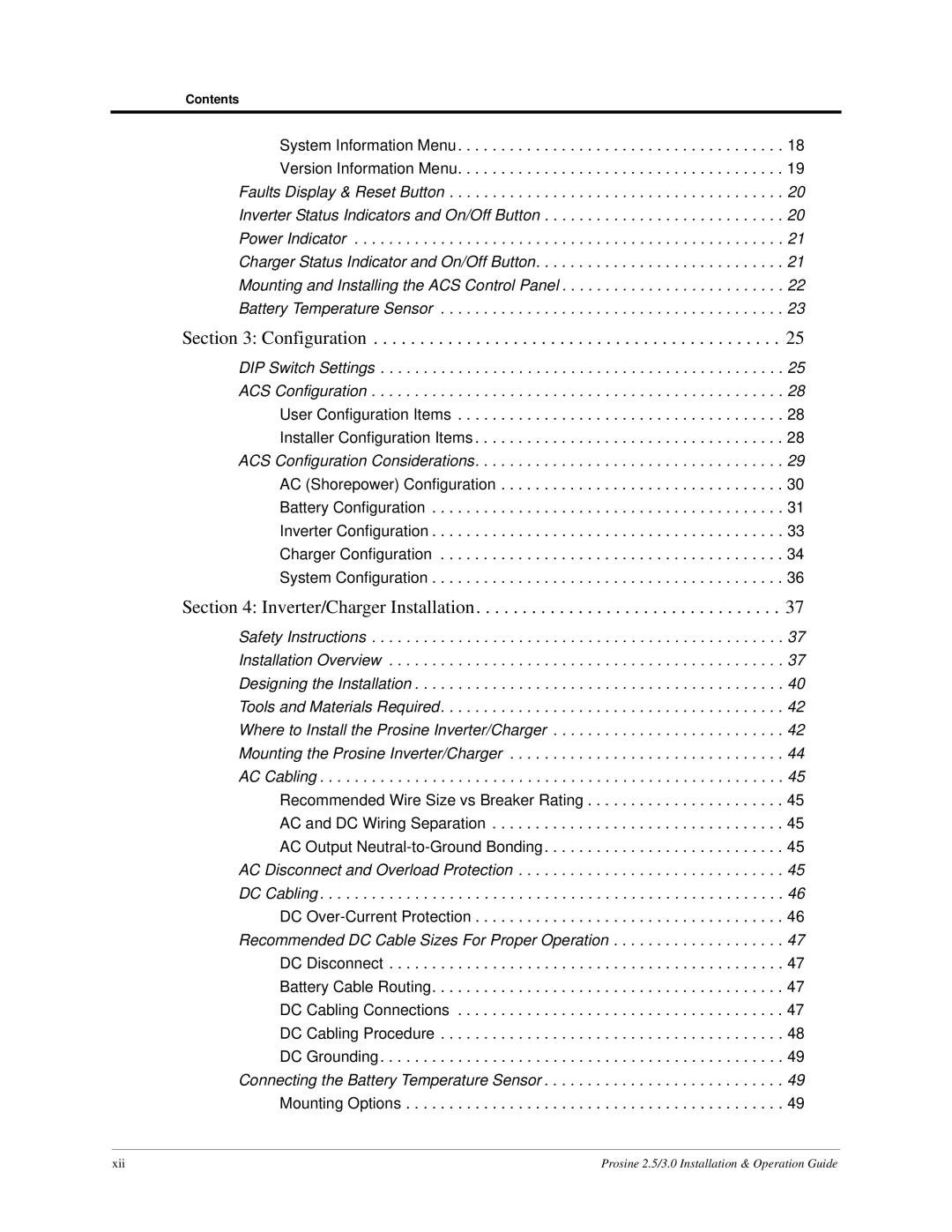
Contents

System Information Menu. . . . . . . . . . . . . . . . . . . . . . . . . . . . . . . . . . . . . . 18

Version Information Menu. . . . . . . . . . . . . . . . . . . . . . . . . . . . . . . . . . . . . . 19

Faults Display & Reset Button . . . . . . . . . . . . . . . . . . . . . . . . . . . . . . . . . . . . . . . 20

Inverter Status Indicators and On/Off Button . . . . . . . . . . . . . . . . . . . . . . . . . . . . 20

Power Indicator . . . . . . . . . . . . . . . . . . . . . . . . . . . . . . . . . . . . . . . . . . . . . . . . . . 21

Charger Status Indicator and On/Off Button. . . . . . . . . . . . . . . . . . . . . . . . . . . . . 21

Mounting and Installing the ACS Control Panel . . . . . . . . . . . . . . . . . . . . . . . . . . 22

Battery Temperature Sensor . . . . . . . . . . . . . . . . . . . . . . . . . . . . . . . . . . . . . . . . 23

Section 3: Configuration . . . . . . . . . . . . . . . . . . . . . . . . . . . . . . . . . . . . . . . . . . . . 25

DIP Switch Settings . . . . . . . . . . . . . . . . . . . . . . . . . . . . . . . . . . . . . . . . . . . . . . . 25

ACS Configuration . . . . . . . . . . . . . . . . . . . . . . . . . . . . . . . . . . . . . . . . . . . . . . . . 28

User Configuration Items . . . . . . . . . . . . . . . . . . . . . . . . . . . . . . . . . . . . . . 28

Installer Configuration Items . . . . . . . . . . . . . . . . . . . . . . . . . . . . . . . . . . . . 28

ACS Configuration Considerations. . . . . . . . . . . . . . . . . . . . . . . . . . . . . . . . . . . . 29

AC (Shorepower) Configuration . . . . . . . . . . . . . . . . . . . . . . . . . . . . . . . . . 30

Battery Configuration . . . . . . . . . . . . . . . . . . . . . . . . . . . . . . . . . . . . . . . . . 31

Inverter Configuration . . . . . . . . . . . . . . . . . . . . . . . . . . . . . . . . . . . . . . . . . 33

Charger Configuration . . . . . . . . . . . . . . . . . . . . . . . . . . . . . . . . . . . . . . . . 34

System Configuration . . . . . . . . . . . . . . . . . . . . . . . . . . . . . . . . . . . . . . . . . 36

Section 4: Inverter/Charger Installation. . . . . . . . . . . . . . . . . . . . . . . . . . . . . . . . . 37

Safety Instructions . . . . . . . . . . . . . . . . . . . . . . . . . . . . . . . . . . . . . . . . . . . . . . . . 37 Installation Overview . . . . . . . . . . . . . . . . . . . . . . . . . . . . . . . . . . . . . . . . . . . . . . 37 Designing the Installation . . . . . . . . . . . . . . . . . . . . . . . . . . . . . . . . . . . . . . . . . . . 40 Tools and Materials Required. . . . . . . . . . . . . . . . . . . . . . . . . . . . . . . . . . . . . . . . 42 Where to Install the Prosine Inverter/Charger . . . . . . . . . . . . . . . . . . . . . . . . . . . 42 Mounting the Prosine Inverter/Charger . . . . . . . . . . . . . . . . . . . . . . . . . . . . . . . . 44 AC Cabling . . . . . . . . . . . . . . . . . . . . . . . . . . . . . . . . . . . . . . . . . . . . . . . . . . . . . . 45

Recommended Wire Size vs Breaker Rating . . . . . . . . . . . . . . . . . . . . . . . 45 AC and DC Wiring Separation . . . . . . . . . . . . . . . . . . . . . . . . . . . . . . . . . . 45 AC Output Neutral-to-Ground Bonding. . . . . . . . . . . . . . . . . . . . . . . . . . . . 45

AC Disconnect and Overload Protection . . . . . . . . . . . . . . . . . . . . . . . . . . . . . . . 45 DC Cabling . . . . . . . . . . . . . . . . . . . . . . . . . . . . . . . . . . . . . . . . . . . . . . . . . . . . . . 46 DC Over-Current Protection . . . . . . . . . . . . . . . . . . . . . . . . . . . . . . . . . . . . 46 Recommended DC Cable Sizes For Proper Operation . . . . . . . . . . . . . . . . . . . . 47 DC Disconnect . . . . . . . . . . . . . . . . . . . . . . . . . . . . . . . . . . . . . . . . . . . . . . 47 Battery Cable Routing. . . . . . . . . . . . . . . . . . . . . . . . . . . . . . . . . . . . . . . . . 47 DC Cabling Connections . . . . . . . . . . . . . . . . . . . . . . . . . . . . . . . . . . . . . . 47 DC Cabling Procedure . . . . . . . . . . . . . . . . . . . . . . . . . . . . . . . . . . . . . . . . 48 DC Grounding. . . . . . . . . . . . . . . . . . . . . . . . . . . . . . . . . . . . . . . . . . . . . . . 49

Connecting the Battery Temperature Sensor . . . . . . . . . . . . . . . . . . . . . . . . . . . . 49

Mounting Options . . . . . . . . . . . . . . . . . . . . . . . . . . . . . . . . . . . . . . . . . . . . 49

xii

Prosine 2.5/3.0 Installation & Operation Guide

Page 16
Image 16
Xantrex Technology PS3.0, PS2.5 installation and operation guide Configuration

PS3.0, PS2.5 specifications

Xantrex Technology has made significant strides in the power electronics sector with the introduction of their PS2.5 and PS3.0 inverter models. These inverters are designed primarily for solar energy applications, offering reliable and efficient power conversion for residential and commercial solar installations. The PS series stands out in the market due to its advanced features, innovative technologies, and user-friendly characteristics.

One of the main features of the Xantrex PS2.5 and PS3.0 inverters is their high efficiency rating, typically above 97%. This means that a minimal amount of energy is lost during conversion, allowing users to maximize their solar energy utilization. Additionally, these inverters come with a wide input voltage range, making them versatile and capable of handling various solar panel configurations.

Both models are equipped with advanced MPPT (Maximum Power Point Tracking) technology. This feature optimizes the energy output from solar panels by constantly adjusting the operating point to ensure maximum power is extracted, even in variable weather conditions or partial shading. This capability significantly enhances the overall energy harvest from solar systems.

Another notable characteristic is their compact and lightweight design, which facilitates easy installation and integration into existing systems. The inverters are also designed with robust thermal management solutions, ensuring they operate effectively even in high-temperature environments. This durability extends their lifespan and increases reliability, critical factors for any solar installation.

Xantrex has also prioritized user experience with the PS2.5 and PS3.0 models by providing a built-in monitoring system. Users can access real-time data on energy production, performance metrics, and system status through a user-friendly interface. This connectivity allows for quick troubleshooting and maintenance, thus enhancing the overall efficiency of solar energy systems.

Safety is paramount in the design of these inverters. They meet stringent international safety standards and come equipped with comprehensive protection features, including over-voltage, under-voltage, and short-circuit protection. This ensures the inverter operates safely, protecting both the user and the connected solar array.

In summary, Xantrex Technology's PS2.5 and PS3.0 inverters are engineered with cutting-edge features and technologies that cater to the evolving needs of solar energy users. Their efficiency, adaptability, and focus on safety make them an excellent choice for those looking to invest in renewable energy solutions. As the demand for sustainable energy continues to rise, Xantrex is poised to play a significant role in the market with these innovative inverter solutions.