035-18895-000-A-0902

POWER WIRING

￿￿￿￿￿￿￿

￿￿￿￿￿￿￿￿

￿￿￿￿￿￿￿￿￿￿￿￿￿￿

￿￿￿￿￿￿￿￿￿￿￿￿￿￿￿￿￿￿￿￿￿￿￿￿￿￿￿￿￿￿￿￿￿￿￿￿￿

￿￿￿￿￿￿￿￿￿￿￿￿￿￿￿￿￿￿￿￿￿￿￿￿￿￿￿￿￿￿￿￿￿￿￿￿￿￿￿

￿￿￿￿￿￿￿￿￿￿￿￿￿￿￿￿￿￿￿￿￿￿￿

￿￿￿￿￿￿￿￿￿￿￿￿￿￿

￿￿￿￿￿￿￿￿￿￿￿￿￿￿￿

￿￿￿

￿￿￿￿￿

￿￿￿￿￿

￿￿￿￿￿

￿￿￿￿￿￿

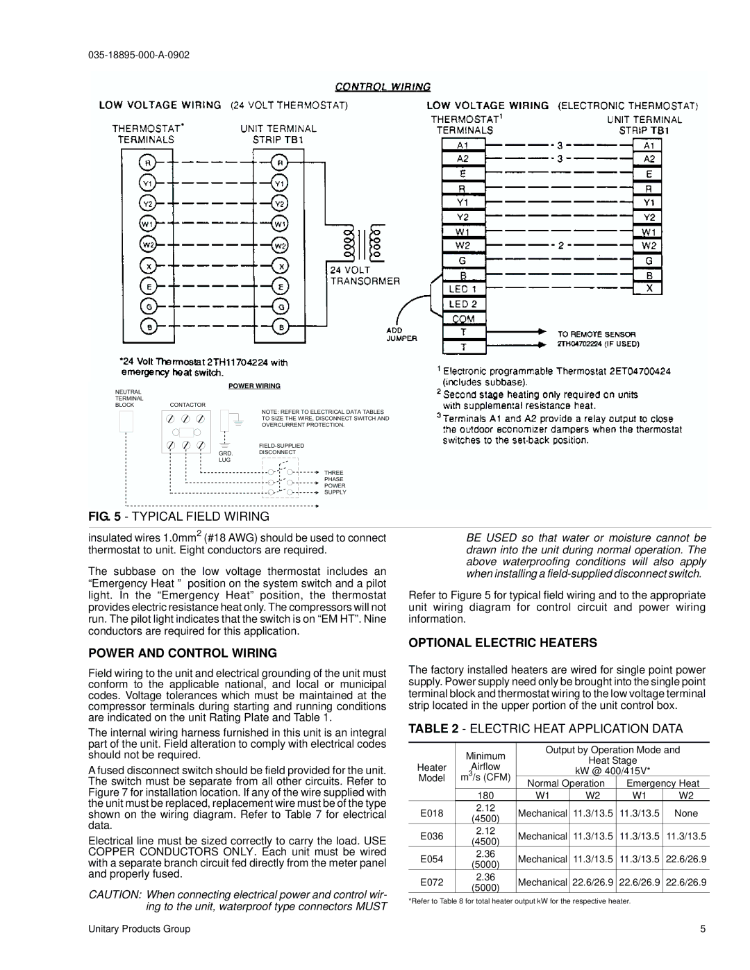
FIG. 5 - TYPICAL FIELD WIRING

insulated wires 1.0mm2 (#18 AWG) should be used to connect thermostat to unit. Eight conductors are required.

The subbase on the low voltage thermostat includes an “Emergency Heat ” position on the system switch and a pilot light. In the “Emergency Heat” position, the thermostat provides electric resistance heat only. The compressors will not run. The pilot light indicates that the switch is on “EM HT”. Nine conductors are required for this application.

POWER AND CONTROL WIRING

Field wiring to the unit and electrical grounding of the unit must conform to the applicable national, and local or municipal codes. Voltage tolerances which must be maintained at the compressor terminals during starting and running conditions are indicated on the unit Rating Plate and Table 1.

The internal wiring harness furnished in this unit is an integral part of the unit. Field alteration to comply with electrical codes should not be required.

A fused disconnect switch should be field provided for the unit. The switch must be separate from all other circuits. Refer to Figure 7 for installation location. If any of the wire supplied with the unit must be replaced, replacement wire must be of the type shown on the wiring diagram. Refer to Table 7 for electrical data.

Electrical line must be sized correctly to carry the load. USE COPPER CONDUCTORS ONLY. Each unit must be wired with a separate branch circuit fed directly from the meter panel and properly fused.

CAUTION: When connecting electrical power and control wir- ing to the unit, waterproof type connectors MUST

BE USED so that water or moisture cannot be drawn into the unit during normal operation. The above waterproofing conditions will also apply when installing a field-supplied disconnect switch.

Refer to Figure 5 for typical field wiring and to the appropriate unit wiring diagram for control circuit and power wiring information.

OPTIONAL ELECTRIC HEATERS

The factory installed heaters are wired for single point power supply. Power supply need only be brought into the single point terminal block and thermostat wiring to the low voltage terminal strip located in the upper portion of the unit control box.

TABLE 2 - ELECTRIC HEAT APPLICATION DATA


Minimum

Output by Operation Mode and


Heat Stage


Heater

Airflow


kW @ 400/415V*


Model

m3/s (CFM)


Normal Operation

Emergency Heat


180

W1

W2

W1

W2

E018

2.12

Mechanical

11.3/13.5

11.3/13.5

None

(4500)


E036

2.12

Mechanical

11.3/13.5

11.3/13.5

11.3/13.5

(4500)


E054

2.36

Mechanical

11.3/13.5

11.3/13.5

22.6/26.9

(5000)


E072

2.36

Mechanical

22.6/26.9

22.6/26.9

22.6/26.9

(5000)


*Refer to Table 8 for total heater output kW for the respective heater.

Unitary Products Group

5

Page 5
Image 5
York B2CH180 installation instructions Power and Control Wiring, Optional Electric Heaters

B2CH180 specifications

The York B2CH180 is a notable addition to the world of commercial heating and cooling systems, designed to meet the demands of a wide range of applications. As part of a renowned legacy in HVAC (Heating, Ventilation, and Air Conditioning) solutions, the B2CH180 unit brings a combination of efficiency, reliability, and innovative technology to ensure optimal performance.

At its core, the York B2CH180 features a high-efficiency, two-stage compressor that significantly enhances its operational effectiveness. This design not only enables precise temperature control but also ensures quieter operation, making it suitable for various environments, including schools, offices, and retail spaces. The two-stage compressor operates at different capacity levels, allowing for better modulation of the system's output based on real-time demands.

One of the standout characteristics of the B2CH180 is its exceptional energy efficiency. With advanced SEER (Seasonal Energy Efficiency Ratio) ratings, this unit helps users to lower energy costs while minimizing their environmental footprint. The use of eco-friendly refrigerants, compliant with the latest regulations, further emphasizes York’s commitment to sustainability.

In terms of control technologies, the York B2CH180 integrates sophisticated smart controls that allow for seamless connection to building management systems. These controls facilitate remote monitoring and adjustment, providing facility managers with valuable insights into operational efficiencies. They can also enable predictive maintenance, alerting users to potential issues before they escalate.

Additionally, this model prioritizes ease of installation and maintenance. Its modular design and accessible components ensure that technicians can perform required services quickly, reducing downtime and enhancing system reliability. The durable construction of the B2CH180, including weather-resistant housing and corrosion-inhibiting coatings, contributes to its long lifespan and low maintenance needs.

The York B2CH180 is also compatible with various accessories and add-ons, allowing for customization based on specific heating and cooling needs. Its versatile application range makes it suitable not only for commercial spaces but also for industrial uses, where powerful performance is essential.

In conclusion, the York B2CH180 is a cutting-edge solution that embodies efficiency, innovative technology, and user-friendly features, making it a top choice for businesses looking to optimize their HVAC systems and enhance occupant comfort.