036-21300-002-A-0905

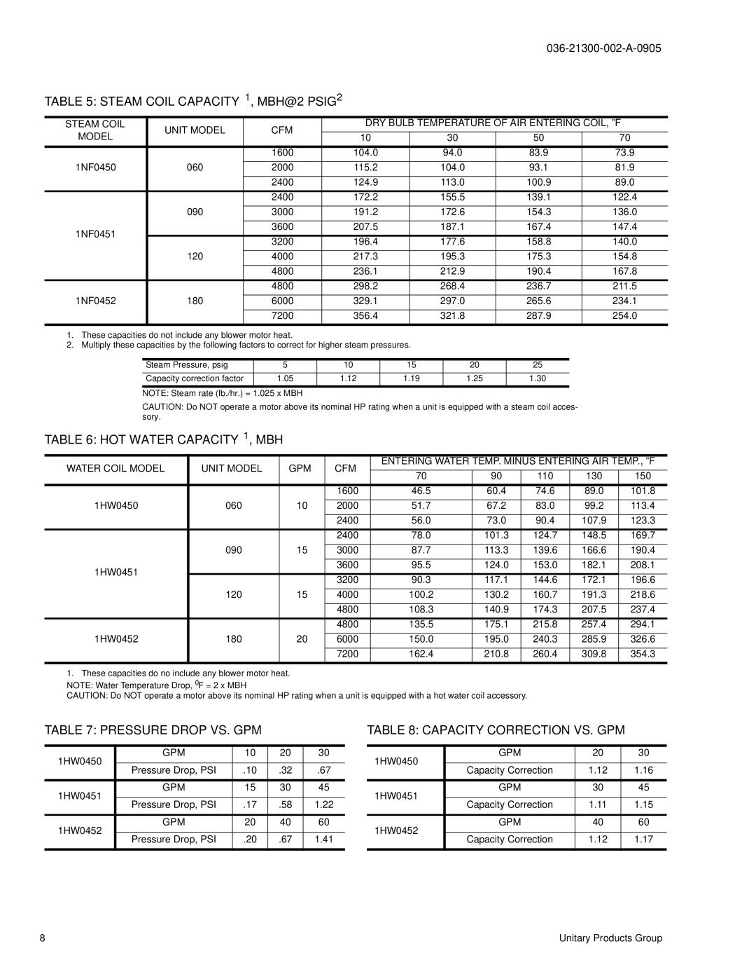
TABLE 5: STEAM COIL CAPACITY1, MBH@2 PSIG2

STEAM COIL

UNIT MODEL

CFM

DRY BULB TEMPERATURE OF AIR ENTERING COIL, ºF

MODEL

10

30

50

70


1600

104.0

94.0

83.9

73.9

1NF0450

060


2000

115.2

104.0

93.1

81.9


2400

124.9

113.0

100.9

89.0


2400

172.2

155.5

139.1

122.4


090


3000

191.2

172.6

154.3

136.0

1NF0451


3600

207.5

187.1

167.4

147.4


3200

196.4

177.6

158.8

140.0


120

4000

217.3

195.3

175.3

154.8


4800

236.1

212.9

190.4

167.8


4800

298.2

268.4

236.7

211.5

1NF0452

180


6000

329.1

297.0

265.6

234.1


7200

356.4

321.8

287.9

254.0

1.These capacities do not include any blower motor heat.

2.Multiply these capacities by the following factors to correct for higher steam pressures.


Steam Pressure, psig


5

10


15

20


25


Capacity correction factor


1.05

1.12


1.19

1.25


1.30


NOTE: Steam rate (lb./hr.) =

1.025 x MBH


CAUTION: Do NOT operate a motor above its nominal HP rating when a unit is equipped with a steam coil acces-


sory.


TABLE 6: HOT WATER CAPACITY1, MBH


WATER COIL MODEL

UNIT MODEL


GPM


CFM


ENTERING WATER TEMP. MINUS ENTERING AIR TEMP., ºF


70


90


110


130

150


1600


46.5


60.4


74.6


89.0

101.8

1HW0450

060


10


2000


51.7


67.2


83.0


99.2

113.4


2400


56.0


73.0


90.4


107.9

123.3


2400


78.0


101.3

124.7


148.5

169.7


090


15


3000


87.7


113.3

139.6


166.6

190.4

1HW0451


3600


95.5


124.0

153.0


182.1

208.1


3200


90.3


117.1

144.6


172.1

196.6


120


15


4000


100.2


130.2

160.7


191.3

218.6


4800


108.3


140.9

174.3


207.5

237.4


4800


135.5


175.1

215.8


257.4

294.1

1HW0452

180


20


6000


150.0


195.0

240.3


285.9

326.6


7200


162.4


210.8

260.4


309.8

354.3

1. These capacities do no include any blower motor heat.

NOTE: Water Temperature Drop, 0F = 2 x MBH

CAUTION: Do NOT operate a motor above its nominal HP rating when a unit is equipped with a hot water coil accessory.

TABLE 7: PRESSURE DROP VS. GPM

1HW0450

GPM

10

20

30


Pressure Drop, PSI

.10

.32

.67


1HW0451

GPM

15

30

45


Pressure Drop, PSI

.17

.58

1.22


1HW0452

GPM

20

40

60


Pressure Drop, PSI

.20

.67

1.41


TABLE 8: CAPACITY CORRECTION VS. GPM

1HW0450

GPM

20

30


Capacity Correction

1.12

1.16


1HW0451

GPM

30

45


Capacity Correction

1.11

1.15


1HW0452

GPM

40

60


Capacity Correction

1.12

1.17


8

Unitary Products Group

Page 8
Image 8
York K2EU060, K3EU120 Steam Coil CAPACITY1, MBH@2 PSIG2, HOT Water CAPACITY1, MBH, Pressure Drop VS. GPM, Unit Model CFM

K3EU180, K4EU090, K3EU120, K2EU060 specifications

The York K3EU120, K2EU060, K3EU180, and K4EU090 are part of York's innovative lineup of HVAC systems, designed for energy efficiency, reliability, and cutting-edge technology. These models cater to various residential and commercial applications, providing optimal climate control while minimizing energy consumption.

The York K3EU120 is designed for medium to large commercial spaces. One of its main features is the advanced inverter-driven compressor technology, which allows for variable speed operation. This ensures that the system only consumes energy as needed, adapting to the specific heating and cooling demands. Additionally, it boasts a high energy efficiency ratio (EER) and seasonal energy efficiency ratio (SEER) ratings, making it an excellent choice for reducing overall operational costs.

The K2EU060 is engineered for smaller commercial applications, such as offices and retail spaces. This model includes a compact design, making it easy to install in tight spaces. It features a low noise operation, promoting a comfortable environment without disrupting business activities. The unit also includes smart controls that allow for remote monitoring and adjustments, enhancing user convenience and energy management.

The K3EU180 model is a heavy-duty unit designed for larger facilities that require robust performance. It is equipped with advanced refrigerant management systems, ensuring optimal cooling efficiency and compliance with environmental regulations. The unit also integrates seamlessly with building management systems (BMS), allowing operators to manage multiple HVAC units from a single interface. This level of connectivity enhances operational efficiency and helps in predictive maintenance by monitoring system performance.

Lastly, the K4EU090 is versatile, making it suitable for various applications including light commercial and multi-family buildings. It highlights energy recovery options, which recycles waste heat to provide additional heating, improving the overall efficiency of the system. This model also features advanced filtration systems that enhance indoor air quality by reducing airborne particles, allergens, and pollutants.

Overall, each of these York models showcases a commitment to forward-thinking HVAC solutions that prioritize energy efficiency, ease of use, and environmental responsibility. Through advanced technologies and innovative features, the York K3EU120, K2EU060, K3EU180, and K4EU090 stand out in their class and offer long-term benefits for end-users.