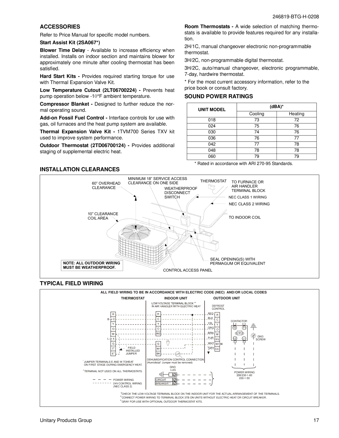
E*BD-(T, E*BD-F018 THRU 060, W)036 THRU 060 specifications
The York W)036 THRU 060, E*BD-F018 THRU 060, E*BD-(T series represents a significant advancement in commercial HVAC solutions, designed to meet the varied needs of large spaces that require efficient climate control. These units are particularly suited for industrial and institutional applications, where reliability and performance are paramount.One of the main features of this series is its energy efficiency. With advanced engineering, these HVAC systems achieve a high Energy Efficiency Ratio (EER) and Seasonal Energy Efficiency Ratio (SEER), which in turn helps businesses reduce their energy bills while minimizing their environmental footprint. The systems are equipped with high-efficiency compressors and optimized refrigerant management strategies to maximize operational effectiveness.
Furthermore, the W)036 THRU 060, E*BD models are designed for flexibility in installation and integration. They can accommodate various building layouts and are compatible with multiple ventilation configurations. This adaptability makes them suitable for warehouses, educational institutions, and large retail facilities.
The technology embedded within these units is state-of-the-art. They include microprocessor-based controls that provide precise temperature management and real-time diagnostics. This smart technology facilitates easier scheduling and monitoring, allowing facility managers to optimize performance according to demand. Additionally, with features such as variable speed fan motors, these systems are able to adjust airflow based on real-time conditions, further enhancing comfort levels while saving energy.
Durability is another hallmark of the W)036 THRU 060, E*BD series. Constructed with robust materials, these units are designed to withstand the rigors of commercial use while requiring minimal maintenance. This reliability ensures that operations remain uninterrupted, which is critical for businesses that rely on consistent climate control.
In terms of environmental impact, these units adhere to stringent industry standards. They utilize eco-friendly refrigerants, which not only comply with regulations but also contribute to lower greenhouse gas emissions.
In summary, the York W)036 THRU 060, E*BD-F018 THRU 060, E*BD-(T series is a prime example of advanced HVAC technology. With features highlighting energy efficiency, flexible installation options, smart technology, and durability, these units are engineered to deliver reliable performance, making them an ideal choice for any commercial application needing superior climate control.

