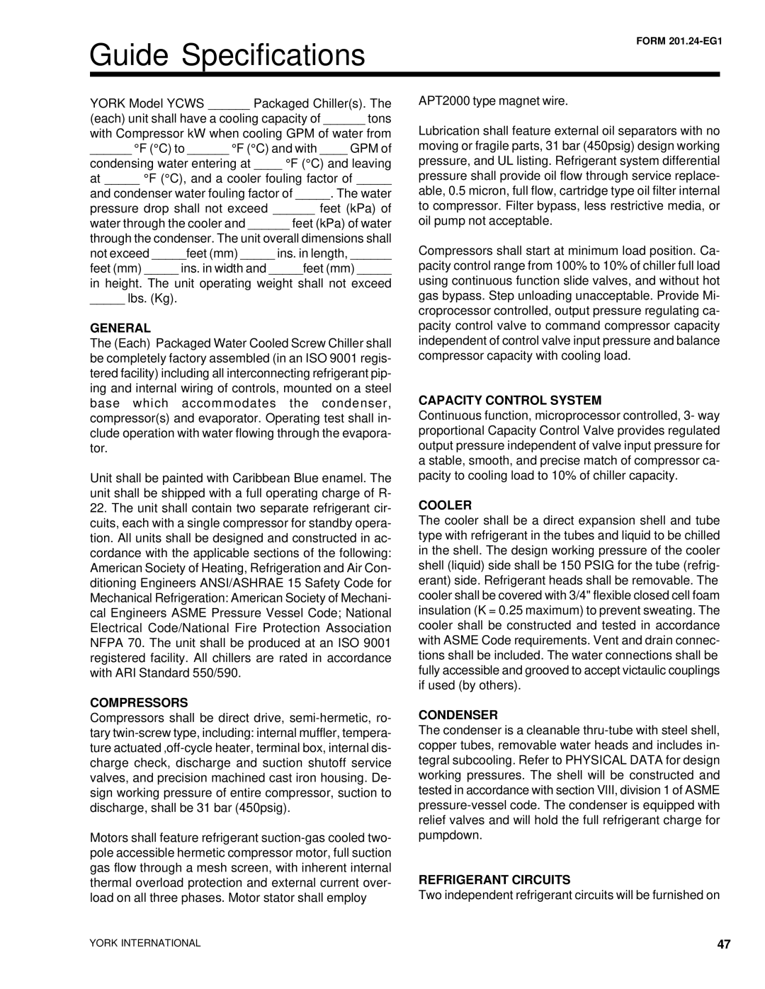
YCWS specifications
York YCWS, or York Chilled Water System, represents a revolutionary approach to modern commercial cooling solutions, offering efficiency, reliability, and sustainability. Designed specifically for large-scale applications such as industrial facilities, data centers, and office buildings, the York YCWS aims to optimize energy use while maintaining climatic comfort indoors.One of the standout features of the York YCWS is its advanced chiller technology. Utilizing cutting-edge centrifugal chillers, the system maximizes cooling through a combination of high efficiency and low operational costs. These chillers operate with variable speed drives, allowing them to adjust their output based on the real-time cooling demand. This leads to significant energy savings, especially in fluctuating load conditions, and reduces wear on the equipment, extending its lifespan.
The YCWS also incorporates smart control systems that enhance its overall performance. These controls employ algorithms to anticipate system demands, dynamically balancing the load across multiple chillers and optimizing energy use throughout the day. Integration with building management systems (BMS) allows for seamless communication and remote monitoring, giving facility managers greater oversight and control over their cooling operations.
Sustainability is at the core of the York YCWS design. The system uses environmentally friendly refrigerants that comply with global standards for reducing greenhouse gas emissions. Additionally, the modular design of the chiller units allows for easy upgrades and expansions, accommodating growing cooling needs without necessitating a complete system overhaul. This flexibility supports a more energy-efficient and environmentally responsible operational model.
The system's footprint is relatively compact, allowing it to fit into tighter spaces typically found in urban settings. Furthermore, the YCWS is engineered for quiet operation, minimizing noise disturbances for occupants in and around the building.
Reliability is another key characteristic of the York YCWS. With a focus on durability and performance, these systems are built to function optimally in various environmental conditions. The robust construction and high-quality materials ensure long-term service, reducing the need for frequent maintenance and associated costs.
In summary, the York YCWS is not just a cooling solution but a comprehensive system that embodies modern engineering principles. Its efficiency, sustainability, and adaptability make it a preferred choice for industries looking to invest in their future. With its smart technologies and robust features, the York Chilled Water System is well-equipped to meet the demanding needs of today's commercial cooling challenges.
