SYSTEM ALIGNMENT
DIGITAL DISPLAY SETUP PROCEDURE GEOMETRY CONVERGENCE
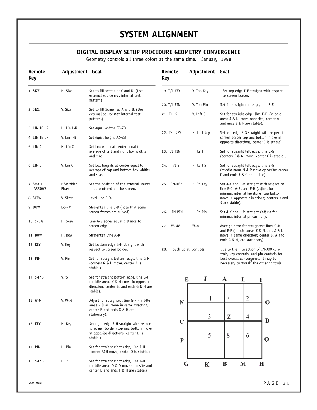
Geometry controls all three colors at the same time. January 1998
Remote | Adjustment | Goal | Remote | Adjustment | Goal | |||||||
Key |
|
| Key |
|
|
|
|
|
|
| ||
|
|
|
|
|
|
|
|
|
|
|
| |
|
|
|
|
|
|
|
|
|
|
|
|
|
1. SIZE | H. Size | Set to fill screen at C and D. (Use |
| 19. T/L KEY | V. Top Key | Set top edge | ||||||
|
| external source not internal test |
|
|
|
|
| to screen border. | ||||
|
| pattern) |
|
|
|
|
|
|
|
|
|
|
|
|
|
| 20. T/L PIN | V. Top Pin | Set for straight top edge, line | ||||||
2. SIZE | V. Size | Set to fill Screen at A and B. (Use |
|
|
|
|
|
|
|
|
|
|
|
| external source not internal test | 21. | T/L S | V. Left S | Set for straight edge, line | ||||||
|
| pattern.) |
|
|
|
|
| areas J & L move opposite; center A | ||||
|
|
|
|
|
|
|
| and ends E & F are stable). | ||||
3. LIN TB LR | H. Lin | Set equal widths CZ=ZD |
|
|
|
|
|
|
|
|
|
|
|
|
| 22. | T/L KEY | H. Left Key | Set left edge | ||||||
4. LIN TB LR | V. Lin | Set equal height AZ=ZB |
|
|
|
|
| screen border top and bottom move in | ||||
|
|
|
|
|
|
|
| opposite directions, center C is stable). | ||||
5. LIN C | H. Lin C | Set box width at center equal to |
|
|
|
|
|
|
|
|
|
|
|
| average of left and right box widths |
| 23. T/L PIN | H. Left Pin | Set for straight left edge, line | ||||||
|
| and size. |
|
|
|
|
| (corners E & G move, center C is stable). | ||||
6. LIN C | V. Lin C | Set box heights at center equal to | 24. | T/L S | H. Left S | Set for straight left edge, line | ||||||
|
| average of top and bottom box widths |
|
|
|
|
| (middle areas N & P move opposite; center | ||||
|
| and size. |
|
|
|
|
| C and ends E & G are stable). | ||||
7. SMALL | H&V Video | Set the position of the external source | 25. | H. In Key | Set | |||||||
ARROWS | Phase | to be centered on the screen. |
|
|
|
|
| line | ||||
|
|
|
|
|
|
|
| minimal internal keystone; top bottom | ||||
8. SKEW | V. Skew | Level line |
|
|
|
|
| move in opposite directions; centers 3 and | ||||
|
|
|
|
|
|
|
| 4 are stable). | ||||
9. BOW | Bow V. | Straighten line |
|
|
|
|
|
|
|
|
|
|
|
| screen frames are curved). | 26. |
| H. In Pin | Set | ||||||
|
|
|
|
|
|
|
| minimal internal pincushion). | ||||
10. SKEW | H. Skew | Line |
|
|
|
|
|
|
|
|
|
|
|
| screen edge. | 27. | Average error for straightest lines | ||||||||
|
|
|
|
|
|
|
| and | ||||
11. BOW | H. Bow | Straighten Line |
|
|
|
|
| move in same direction; center B, A and | ||||
|
|
|
|
|
|
|
| ends G & H, are stationary). | ||||
12. KEY | V. Key | Set bottom edge |
|
|
|
|
|
|
|
|
|
|
|
| respect to screen border. | 28. | Touch up all controls | Due to the interaction of | |||||||
|
|
|
|
|
|
|
| trols, key controls, and pin controls for | ||||
13. PIN | V. Pin | Set for straight bottom edge, line |
|
|
|
|
| best overall convergence, it may be | ||||
|
| (corners G & H move, center B is |
|
|
|
|
| necessary to ‘tweak’ the other controls. | ||||
|
| stable.) |
|
|
|
|
|
|
|
|
|
|
14. | V. ‘S’ | Set for straight bottom edge, line |
|
|
|
|
|
|
|
|
|
|
|
| (middle areas K & M move in opposite |
|
|
|
|
|
|
|
|
|
|
|
| direction, center B; and ends G & H are |
|
|
|
|
|
|
|
|
|
|
|
| stable). |
|
|
|
|
|
|
|
|
|
|
15. | V. | Adjust for straightest line |
|
|
|
|
|
|
|
|
|
|
|
| areas K & M move in same direction, |
|
|
|
|
|
|
|
|
|
|
|
| center B and ends G & H are |
|
|
|
|
|
|
|
|
|
|
|
| stationary). |
|
|
|
|
|
|
|
|
|
|
16. KEY | H. Key | Set right edge |
|
|
|
|
|
|
|
|
|
|
|
|
|
|
|
|
|
|
|
| |||
|
| to screen border (top and bottom move |
|
|
|
|
|
|
|
|
|
|
|
| in opposite directions; center D is |
|
|
|
|
|
|
|
|
|
|
|
| stable.) |
|
|
|
|
|
|
|
|
|
|
17. PIN | H. Pin | Set for straight right edge, line |
|
|
|
|
|
|
|
|
|
|
|
| (corner F&H move, center D is stable.) |
|
|
|
|
|
|
|
|
|
|
18. | H. ‘S’ | Set for straight right edge, line |
|
|
|
|
|
|
|
|
|
|
|
|
|
|
|
|
|
|
|
| |||
|
| (middle areas O & Q move opposite and |
|
|
|
|
|
|
|
|
|
|
|
| center D and ends F & H are stable.) |
|
|
|
|
|
|
|
|
|
|
|
|
|
|
|
|
|
|
|
|
|
|
|
P A G E 2 5 | |
|