SYSTEM ALIGNMENT
Continued from previous page
Verify spot alignment by rotating Green electrical focus slightly
If this test shows a need for astimatator alignment perform steps “a” - “l” below.
Astigmatator Alignment Procedure
a. Set the display/sync mode to Forced Mode 6 (HDTV33) and select a
b. Cut off Red and Blue video or cover the CRT lens assemblies.
c. Set Green electrical focus slightly CCW. This is to make a dot near the display center dimly haloed with a bright center. The haloed effect will also be visible with the
d. Use the astigmatator
e. Use the astigmatator
f. Use the astigmatator
g. Use the main yoke magnets to position the signal raster center to the CRT face center. Refer to figure below.
h. Verify spot alignment by rotating Green electrical focus slightly CW to CCW. The Dot shape should not tail or flair. The bright area should remain in the center of the haloed area.
i. Repeat steps “c” thru “h” as needed to obtain the smallest and best round Green center dot with no shape flaring.
j. Adjust for the best electrical and mechanical focus. k. Repeat steps “c” - “j” for the Red and Blue displays. l. Exit forced mode 6 and return to normal video. Set
Brightness and Contrast to 50.
Note: The yoke adjustments should not be touched during the remaining setup steps.
FOCUS PROCEDURE USING SPRING SYSTEM Changing Preset 80 inch Width Image Screen Size
Note: The PRO895X is shipped preadjusted for an 80 inch project- ed screen size image.
To set up a screen size other than 80 inch width, you must remove the shims from each of the 3 lens assemblies.
Note: Remove AC Power. Be careful not to damage the lens assembly or scratch the lens surface. The lenses can be easily damaged during removal and reinstallation.
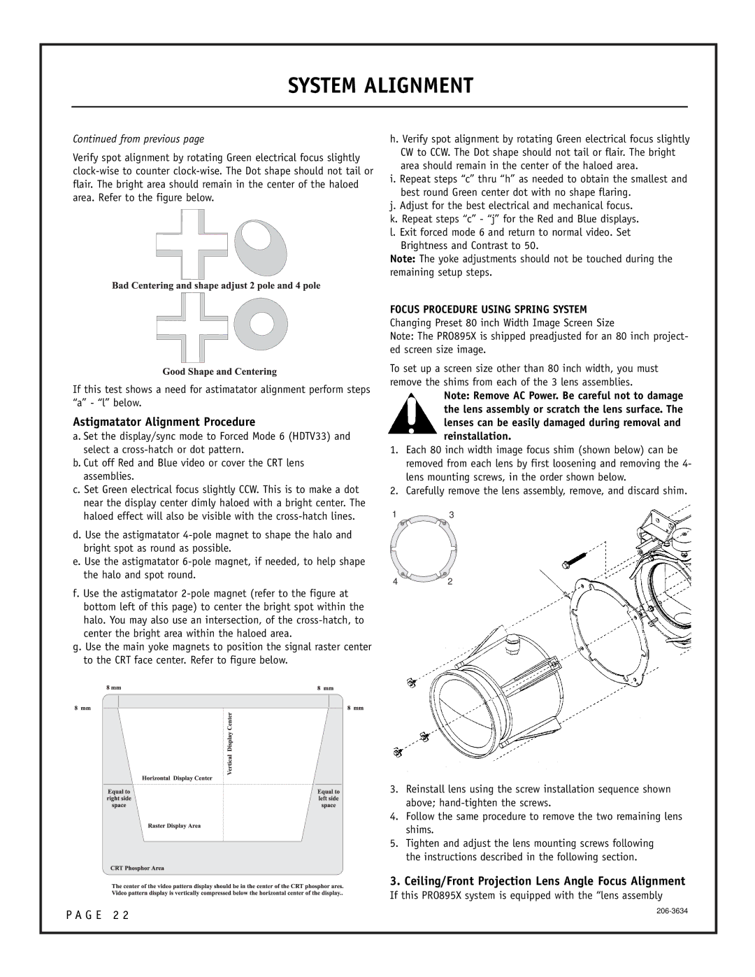
1.Each 80 inch width image focus shim (shown below) can be removed from each lens by first loosening and removing the 4- lens mounting screws, in the order shown below.
2.Carefully remove the lens assembly, remove, and discard shim.
13
42
3.Reinstall lens using the screw installation sequence shown above;
4.Follow the same procedure to remove the two remaining lens shims.
5.Tighten and adjust the lens mounting screws following the instructions described in the following section.
3.Ceiling/Front Projection Lens Angle Focus Alignment
If this PRO895X system is equipped with the “lens assembly
P A G E 2 2 | |
|