SYSTEM ALIGNMENT
|
|
|
|
|
|
|
|
|
|
|
|
|
|
|
|
|
|
|
|
|
|
|
|
|
|
|
|
|
|
|
|
|
|
|
|
|
|
|
|
|
|
|
|
|
|
|
|
|
|
|
|
|
|
|
|
|
|
|
|
|
|
|
|
|
|
|
|
|
|
|
|
|
|
|
|
|
|
|
|
|
|
|
|
|
|
|
|
|
|
|
|
|
|
|
|
|
|
|
|
|
|
|
|
|
|
|
|
|
|
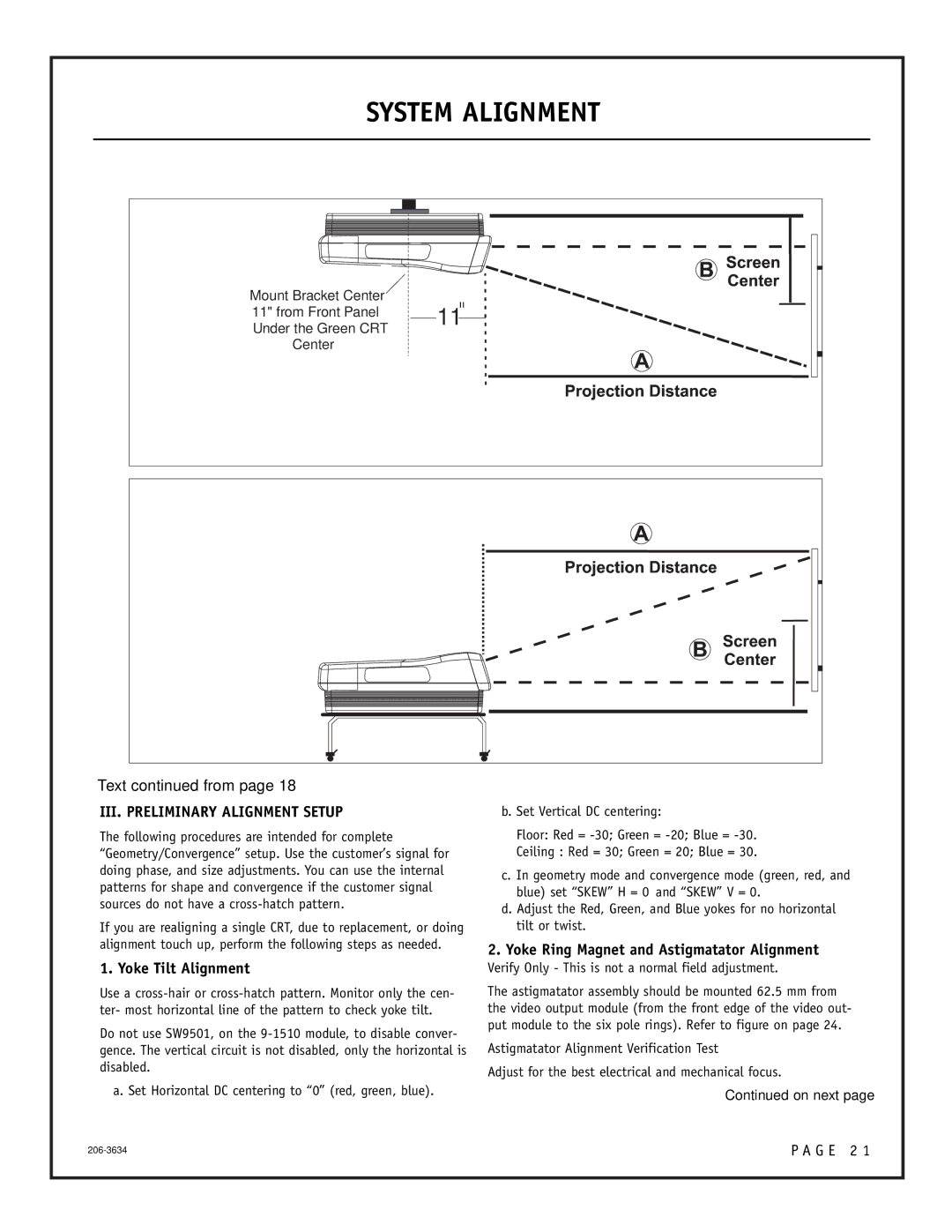
| Mount Bracket Center |
|
|
|
|
| 11 |
|
|
|
|
|
|
|
|
| |||||
|
|
|
|
|
|
|
|
|
|
|
|
|
|
| |||||||
| 11" from Front Panel |
|
|
|
|
|
|
|
|
|
|
|
|
|
| ||||||
| Under the Green CRT |
|
|
|
|
|
|
|
|
|
|
|
|
|
| ||||||
|
|
|
|
|
|
|
|
|
|
|
|
|
|
|
| ||||||
| Center |
|
|
|
|
|
|
|
|
|
|
|
|
|
|
| |||||
|
|
|
|
|
|
|
|
|
|
|
|
|
|
|
|
|
|
|
|
|
|
|
|
|
|
|
|
|
|
|
|
|
|
|
|
|
|
|
|
|
|
|
|
|
|
|
|
|
|
|
|
|
|
|
|
|
|
|
|
|
|
|
|
|
|
|
|
|
|
|
|
|
|
|
|
|
|
|
|
|
|
|
|
|
|
|
|
|
|
|
|
|
|
|
|
|
|
|
|
|
|
|
|
|
|
|
|
|
|
|
|
|
|
|
|
|
|
|
|
|
|
|
|
|
|
|
|
|
|
|
|
|
|
|
|
|
|
|
|
|
|
|
|
|
|
|
|
|
|
|
|
|
|
|
|
|
|
|
|
|
|
|
|
|
|
|
|
|
|
|
|
|
|
|
|
|
|
|
|
|
|
|
|
|
|
|
|
|
|
|
|
|
|
|
|
|
|
|
|
|
|
|
|
|
|
|
|
|
|
|
|
|
|
|
|
|
|
|
|
|
|
|
|
|
|
|
|
|
|
|
|
|
|
|
|
|
|
|
|
|
|
|
|
|
|
|
|
|
|
|
|
|
|
|
|
|
|
|
|
|
|
|
|
|
|
|
|
|
|
|
|
|
|
|
|
|
|
|
|
|
|
|
|
|
|
|
|
|
|
|
|
|
|
|
|
|
|
|
|
|
|
|
|
|
|
|
|
|
|
|
|
|
|
|
|
|
|
|
|
|
|
|
|
|
|
|
|
|
|
|
|
|
|
|
|
|
|
|
|
|
|
|
|
|
|
|
|
|
|
|
|
Text continued from page 18
III. PRELIMINARY ALIGNMENT SETUP
The following procedures are intended for complete “Geometry/Convergence” setup. Use the customer’s signal for doing phase, and size adjustments. You can use the internal patterns for shape and convergence if the customer signal sources do not have a
If you are realigning a single CRT, due to replacement, or doing alignment touch up, perform the following steps as needed.
1. Yoke Tilt Alignment
Use a
Do not use SW9501, on the
a. Set Horizontal DC centering to “0” (red, green, blue).
b. Set Vertical DC centering:
Floor: Red =
Ceiling : Red = 30; Green = 20; Blue = 30.
c. In geometry mode and convergence mode (green, red, and blue) set “SKEW” H = 0 and “SKEW” V = 0.
d. Adjust the Red, Green, and Blue yokes for no horizontal tilt or twist.
2.Yoke Ring Magnet and Astigmatator Alignment
Verify Only - This is not a normal field adjustment.
The astigmatator assembly should be mounted 62.5 mm from the video output module (from the front edge of the video out- put module to the six pole rings). Refer to figure on page 24.
Astigmatator Alignment Verification Test
Adjust for the best electrical and mechanical focus.
Continued on next page
P A G E 2 1 |
