Connections (Continued)
Radio Antenna Connections
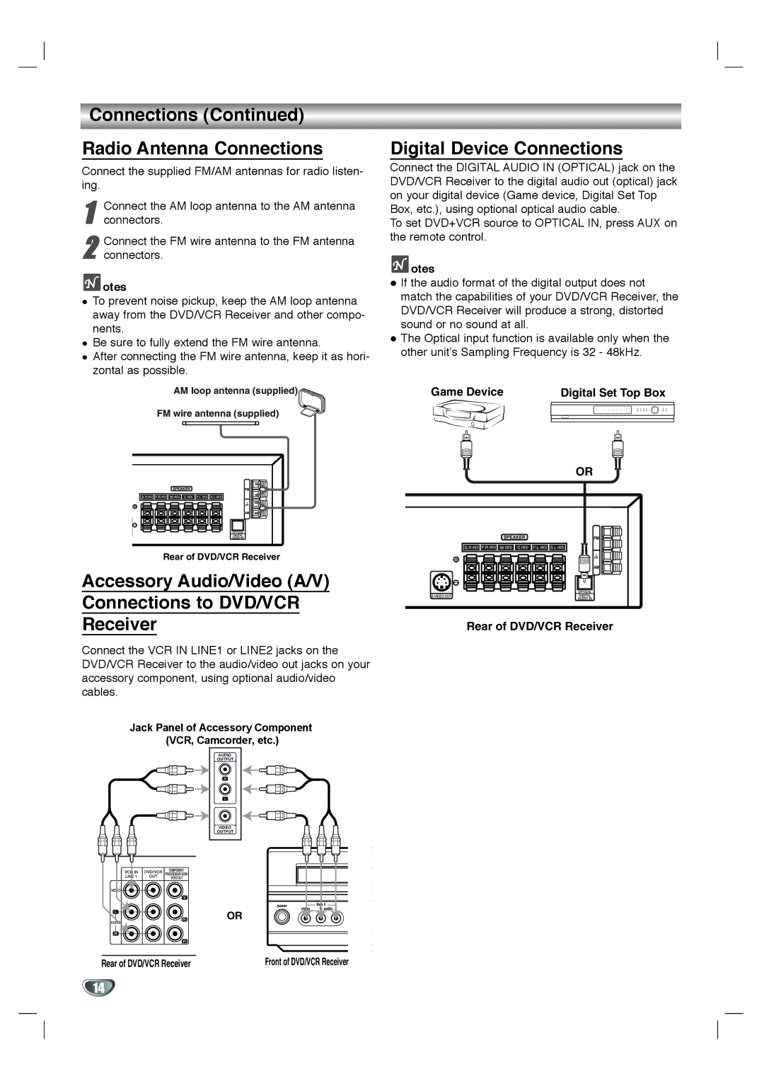
Connect the supplied FM/AM antennas for radio listen- ing.
1 | Connect the AM loop antenna to the AM antenna |
connectors. |
2 Connect the FM wire antenna to the FM antenna connectors.
 otes
otes
To prevent noise pickup, keep the AM loop antenna away from the DVD/VCR Receiver and other compo- nents.
Be sure to fully extend the FM wire antenna.
After connecting the FM wire antenna, keep it as hori- zontal as possible.
AM loop antenna (supplied)
FM wire antenna (supplied)
Rear of DVD/VCR Receiver
Accessory Audio/Video (A/V) Connections to DVD/VCR Receiver
Connect the VCR IN LINE1 or LINE2 jacks on the DVD/VCR Receiver to the audio/video out jacks on your accessory component, using optional audio/video cables.
Jack Panel of Accessory Component (VCR, Camcorder, etc.)
AUDIO
OUTPUT
R
L
VIDEO
OUTPUT
OR
Rear of DVD/VCR Receiver | Front of DVD/VCR Receiver |
Digital Device Connections
Connect the DIGITAL AUDIO IN (OPTICAL) jack on the DVD/VCR Receiver to the digital audio out (optical) jack on your digital device (Game device, Digital Set Top Box, etc.), using optional optical audio cable.
To set DVD+VCR source to OPTICAL IN, press AUX on the remote control.
 otes
otes
If the audio format of the digital output does not match the capabilities of your DVD/VCR Receiver, the DVD/VCR Receiver will produce a strong, distorted sound or no sound at all.
The Optical input function is available only when the other unit’s Sampling Frequency is 32 - 48kHz.
Game Device | Digital Set Top Box | ||
|
|
|
|
|
|
|
|
OR
Rear of DVD/VCR Receiver
14