English
1. Set up
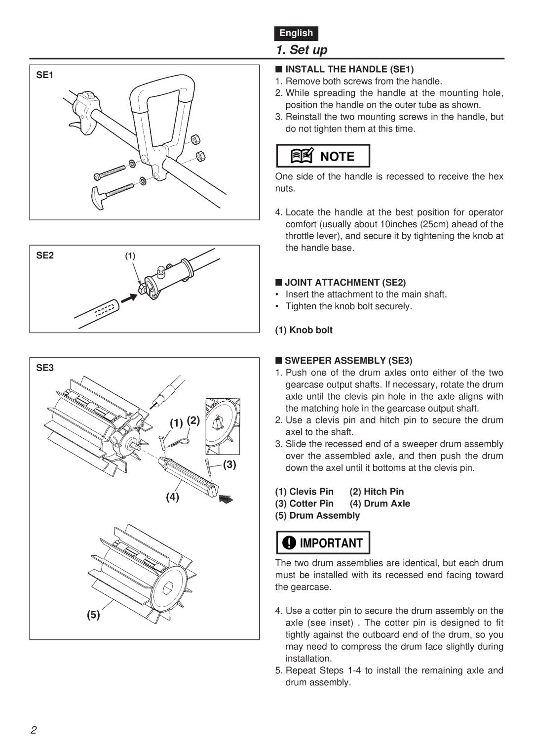
SE1
SE2(1)
SE3
■INSTALL THE HANDLE (SE1)
1.Remove both screws from the handle.
2.While spreading the handle at the mounting hole, position the handle on the outer tube as shown.
3.Reinstall the two mounting screws in the handle, but do not tighten them at this time.
![]() NOTE
NOTE
One side of the handle is recessed to receive the hex nuts.
4.Locate the handle at the best position for operator comfort (usually about 10inches (25cm) ahead of the throttle lever), and secure it by tightening the knob at the handle base.
■JOINT ATTACHMENT (SE2)
•Insert the attachment to the main shaft.
•Tighten the knob bolt securely.
(1) Knob bolt
■SWEEPER ASSEMBLY (SE3)
1.Push one of the drum axles onto either of the two gearcase output shafts. If necessary, rotate the drum axle until the clevis pin hole in the axle aligns with the matching hole in the gearcase output shaft.
2.Use a clevis pin and hitch pin to secure the drum axel to the shaft.
3.Slide the recessed end of a sweeper drum assembly over the assembled axle, and then push the drum down the axel until it bottoms at the clevis pin.
(1) Clevis Pin | (2) | Hitch Pin |
(3) Cotter Pin | (4) | Drum Axle |
(5) Drum Assembly |
| |
![]()
![]() IMPORTANT
IMPORTANT
The two drum assemblies are identical, but each drum must be installed with its recessed end facing toward the gearcase.
4.Use a cotter pin to secure the drum assembly on the axle (see inset) . The cotter pin is designed to fit tightly against the outboard end of the drum, so you may need to compress the drum face slightly during installation.
5.Repeat Steps
2