


Chapter 3: Installation
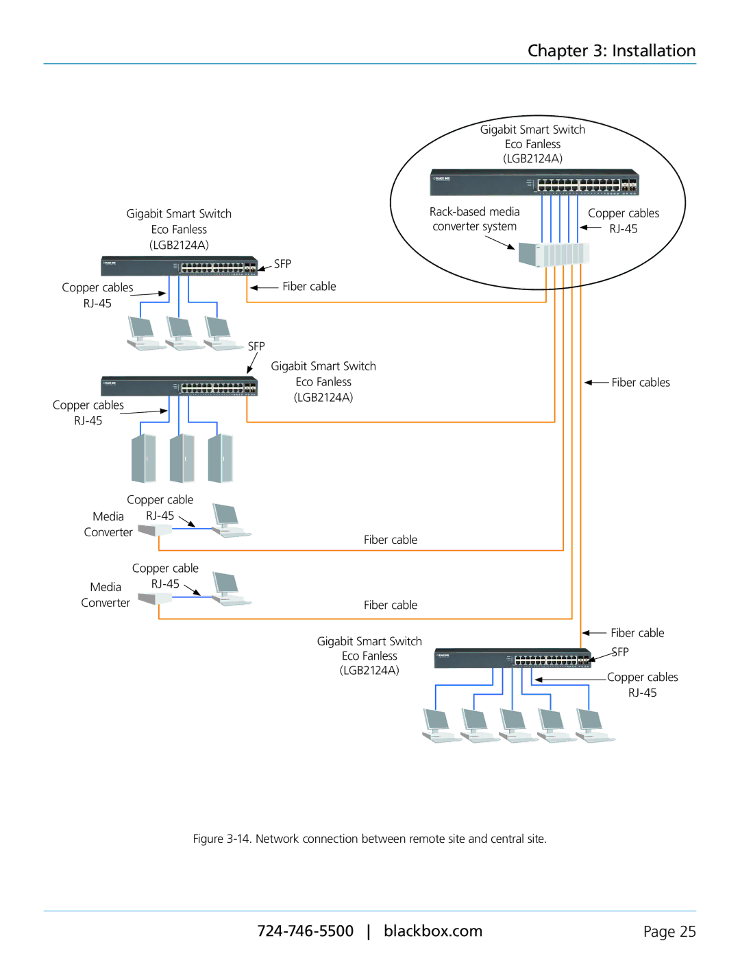
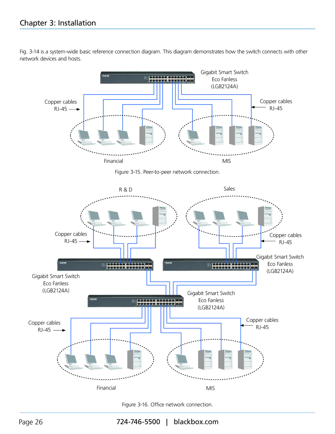
Fig. 3-14 is a system-wide basic reference connection diagram. This diagram demonstrates how the switch connects with other network devices and hosts.
Copper cables RJ-45 
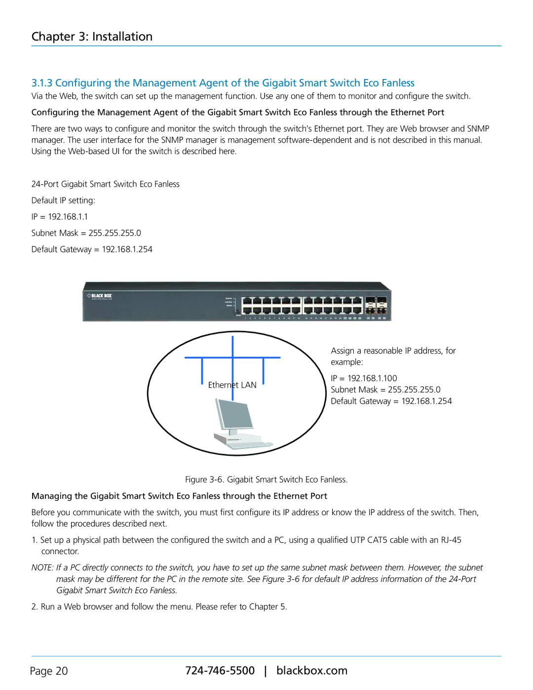
Gigabit Smart Switch
Eco Fanless (LGB2124A)
Copper cables |
Copper cables
RJ-45 
Gigabit Smart Switch
Eco Fanless (LGB2124A)
Copper cables
RJ-45 
Financial | MIS |
Figure 3-15. Peer-to-peer network connection.
R & D | Sales |
Copper cables
Gigabit Smart Switch
Eco Fanless (LGB2124A)
Gigabit Smart Switch
Eco Fanless (LGB2124A)
Copper cables |
Financial | MIS |
Figure 3-16. Office network connection.
Page 26 |