Chapter 4: Basic Concepts and Management
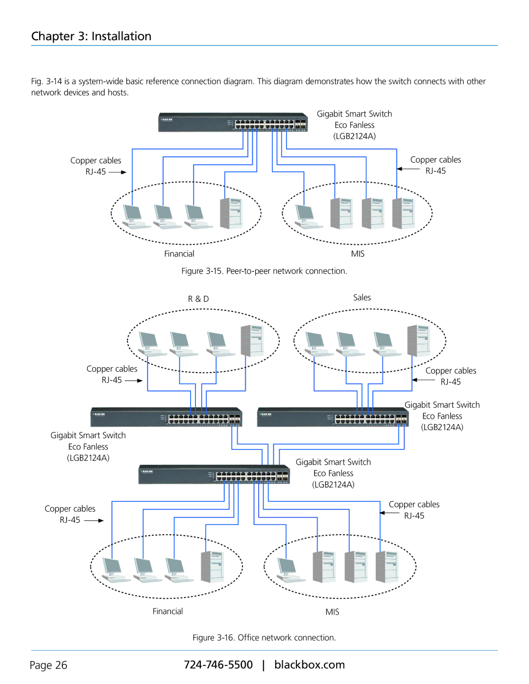
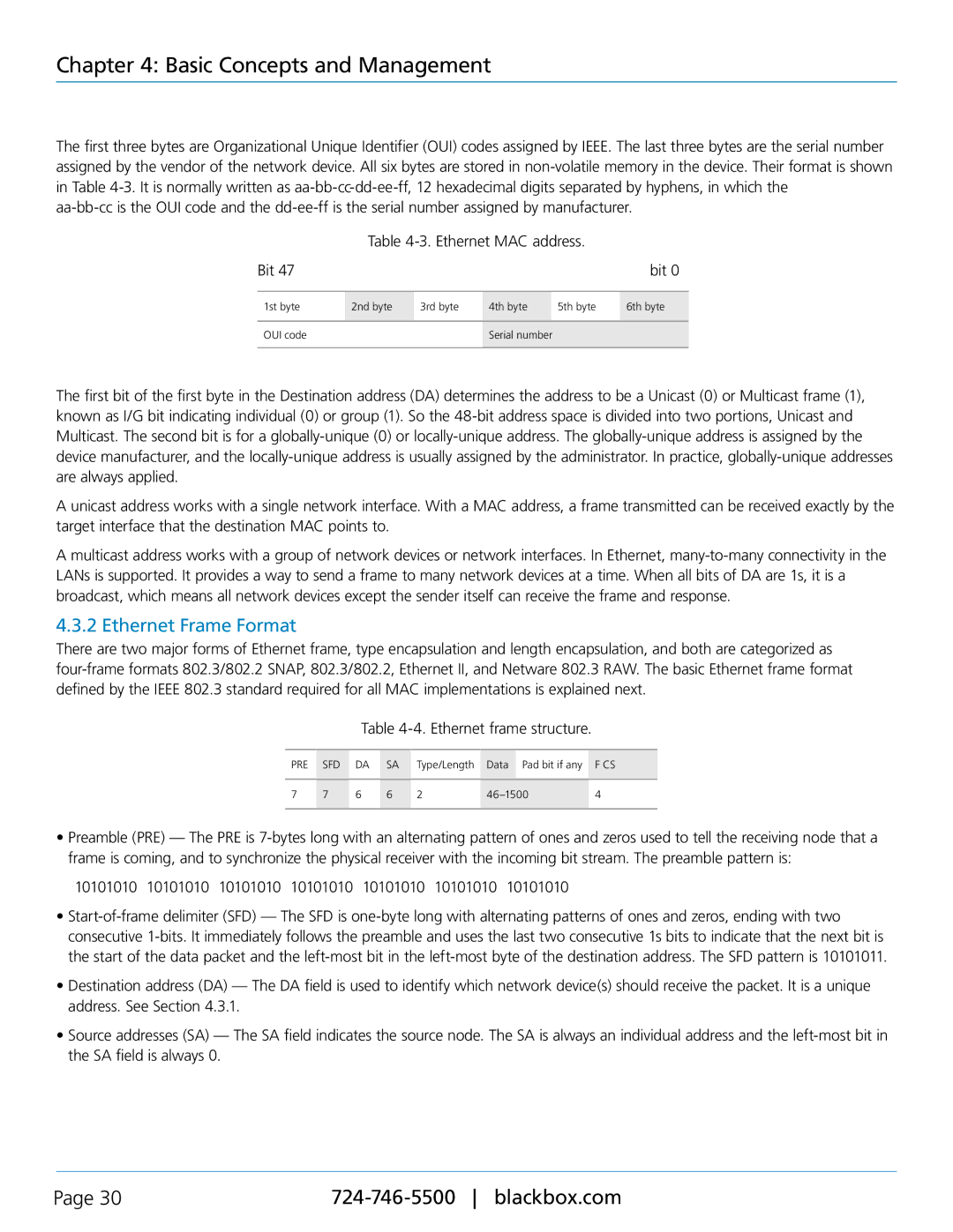
Table 4-5. Ethernet parameters for half-duplex mode.
| Parameter Value/LAN | 10BASE | 100BASE | 1000BASE |
| | | | |
| Max. collision domain DTE to DTE | 328 feet (100 m) | 328 feet (100 m) for UTP | 328 feet (100 m) for UTP |
| 1351.7 feet (412 m) for fiber | 1043.3 feet (316 m) for fiber |
| | |
| | | | |
| Max. collision domain with repeater | 8202.1 feet (2500 m) | 672.6 feet (205 m) | 646.1 feet (200 m) |
| | | | |
| Slot time | 512 bit times | 512 bit times | 512 bit times |
| | | | |
| Interframe gap | 9.6 µs | 0.96 µs | 0.096 µs |
| | | | |
| Attempt Limit | 16 | 16 | 16 |
| | | | |
| Backoff Limit | 10 | 10 | 10 |
| | | | |
| Jam size | 32 bits | 32 bits | 32 bits |
| | | | |
| Max. frame size | 1518 | 1518 | 1518 |
| | | | |
| Min. frame size | 64 | 64 | 64 |
| | | | |
| Burst limit | Not applicable | Not applicable | 65536 bits |
| | | | |
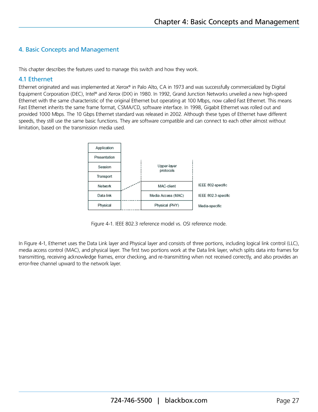
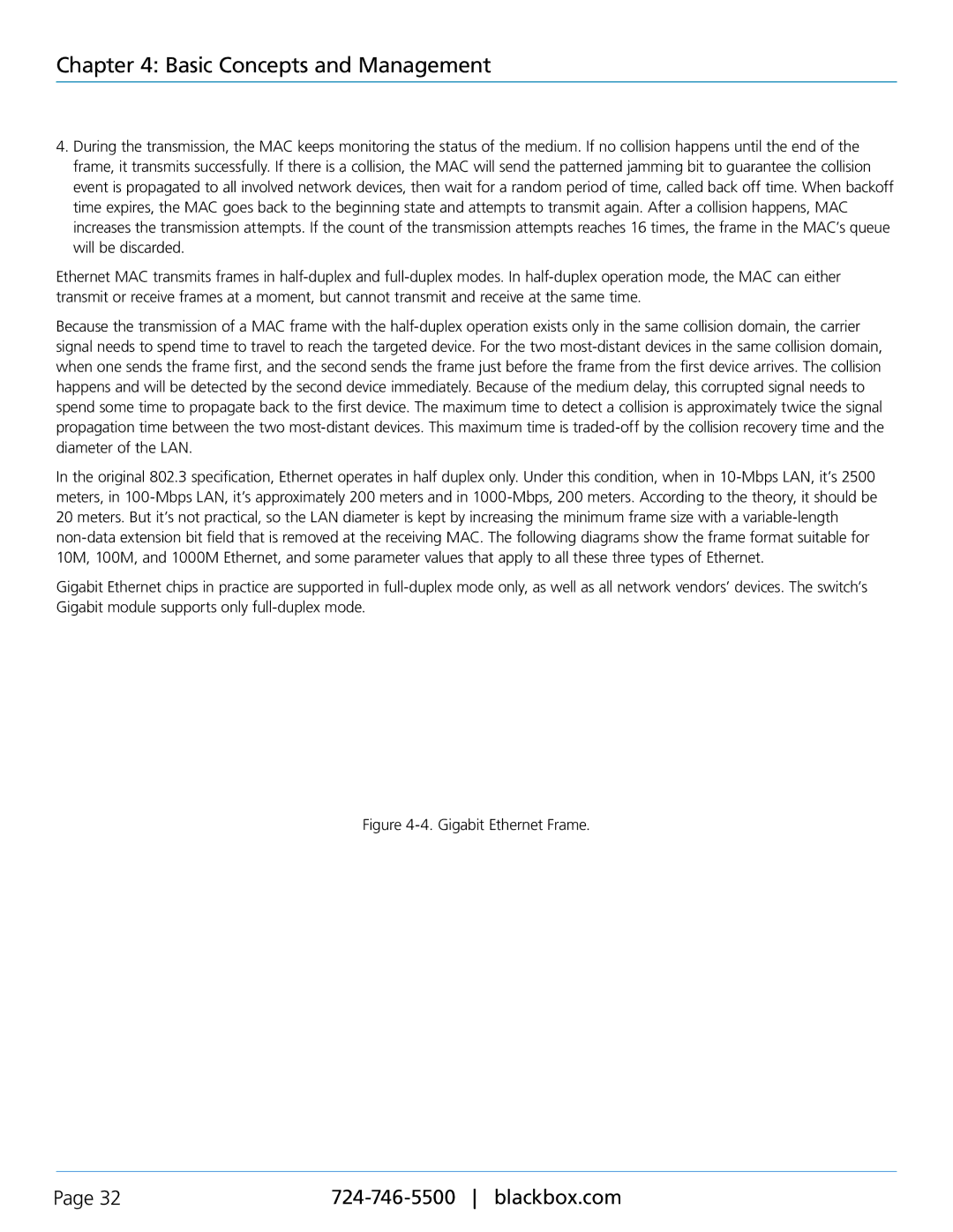
Figure 4-5. Full-duplex mode.
In full-duplex operation mode, both transmitting and receiving frames are processed simultaneously. This doubles the total bandwidth. Full-duplex is much easier than half-duplex because it does not involve media contention, collision, retransmission schedule, and padding bits for short frames. It functions according to the IEEE 802.3 specification. The minimum inter-frame gap requirement between successive frames and frame formats is the same as that in the half-duplex operation.
No collision will happen in full-duplex operation. What happens if the receiving device is busy and a frame is coming at the same time? Can it use “backpressure” to tell the source device? A flow control function is introduced in full-duplex operation.
4.4 Flow Control
Flow control is a mechanism that tells the source device to stop sending frames for a specified period of time designated by a target device until the PAUSE time expires. It does this by sending a PAUSE frame from the target device to the source device. When the target is not busy and the PAUSE time is expired, it will send another PAUSE frame with zero time-to-wait to the source device. After the source device receives the PAUSE frame, it will again transmit frames immediately. The PAUSE frame is identical in the form of the MAC frame with a pause-time value and with a special destination MAC address 01-80-C2-00-00-01. As per the specification, PAUSE operation can not be used to inhibit the transmission of a MAC control frame.
Normally, in 10-Mbps and 100-Mbps Ethernet, only symmetric flow control is supported. However, the Gigabit Smart Switch Eco Fanless supports not only symmetric, but also asymmetric flow control for the special application. In Gigabit Ethernet, both symmetric flow control and asymmetric flow control are supported. Asymmetric flow control only allows transmitting a PAUSE frame in one way from one side; the other side is not transmitted. Instead the switch receives and discards the flow control information. Symmetric flow control allows both two ports to transmit PAUSE frames to each other simultaneously.
724-746-5500 blackbox.com | Page 33 |