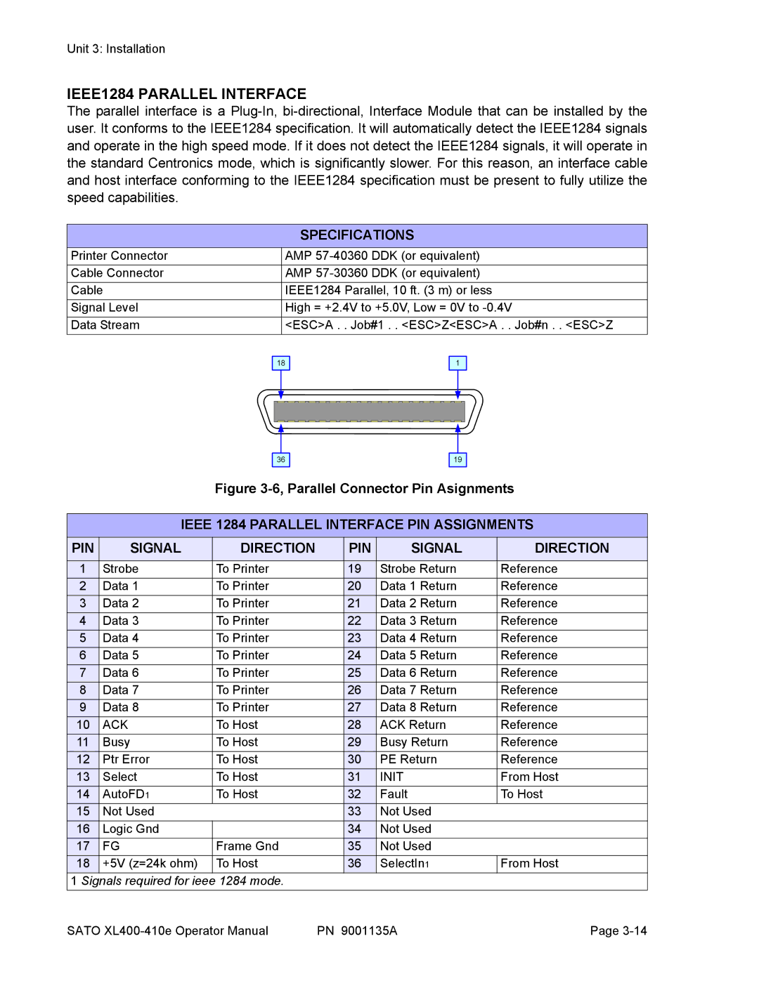
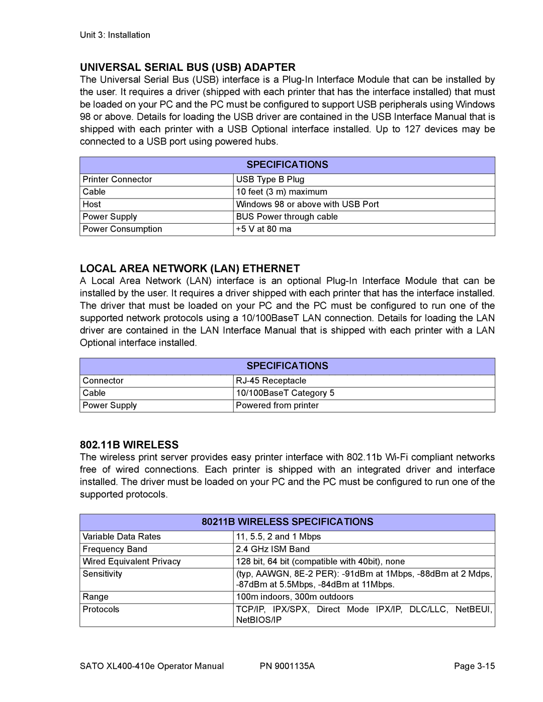
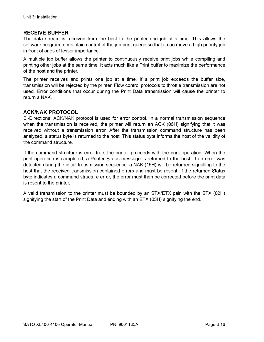
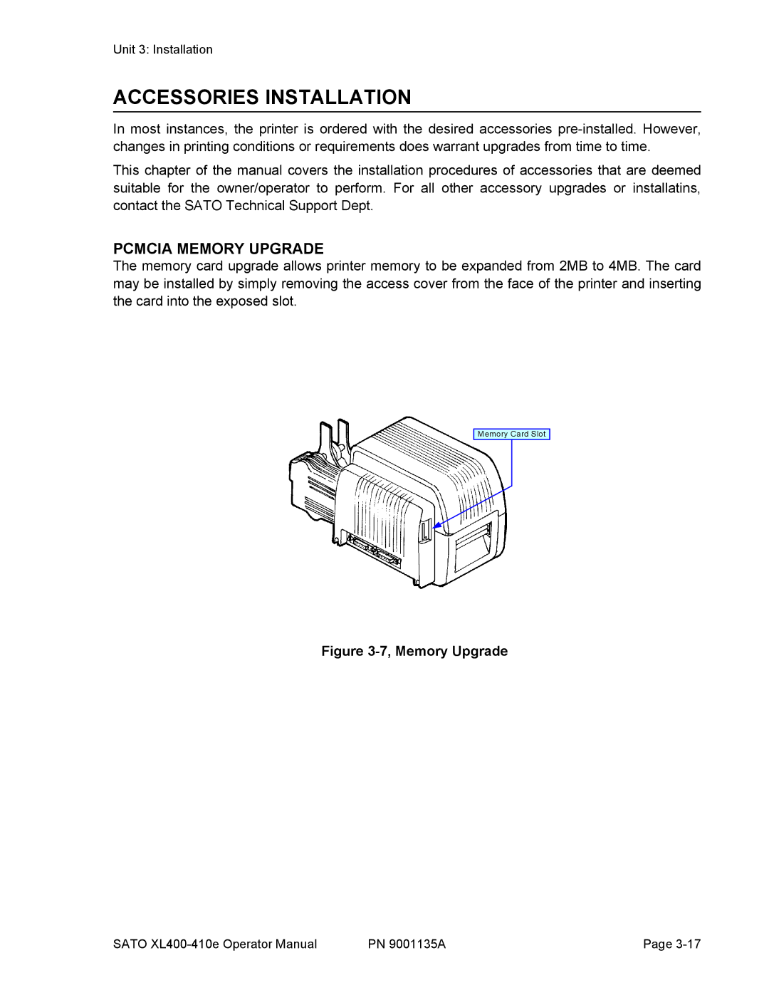
SATO 400e, 410e manual RS232C Serial Interface Signals, PIN Direction Signal Definition

Page 29

Unit 3: Installation


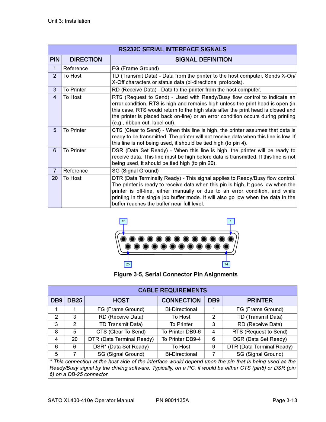
RS232C SERIAL INTERFACE SIGNALS

PIN

DIRECTION

SIGNAL DEFINITION

1

Reference

FG (Frame Ground)

2

To Host

TD (Transmit Data) - Data from the printer to the host computer. Sends X-On/


X-Off characters or status data (bi-directional protocols).

3

To Printer

RD (Receive Data) - Data to the printer from the host computer.

4

To Host

RTS (Request to Send) - Used with Ready/Busy flow control to indicate an


error condition. RTS is high and remains high unless the print head is open (in


this case, RTS would return to the high state after the print head is closed and


the printer is placed back on-line) or an error condition occurs during printing


(e.g., ribbon out, label out).

5

To Printer

CTS (Clear to Send) - When this line is high, the printer assumes that data is


ready to be transmitted. The printer will not receive data when this line is low. If


this line is not being used, it should be tied high (to pin 4).

6

To Printer

DSR (Data Set Ready) - When this line is high, the printer will be ready to


receive data. This line must be high before data is transmitted. If this line is not


being used, it should be tied high (to pin 20).

7

Reference

SG (Signal Ground)

20

To Host

DTR (Data Terminally Ready) - This signal applies to Ready/Busy flow control.


The printer is ready to receive data when this pin is high. It goes low when the


printer is off-line, either manually or due to an error condition, and while


printing in the single job buffer mode. It will also go low when the data in the


buffer reaches the buffer near full level.

13

1

25

14

Figure 3-5, Serial Connector Pin Asignments

CABLE REQUIREMENTS

DB9

DB25

HOST

CONNECTION

DB9

PRINTER

1

1

FG (Frame Ground)

Bi-Directional

1

FG (Frame Ground)

2

3

RD (Receive Data)

To Host

2

TD (Transmit Data)

3

2

TD Transmit Data)

To Printer

3

RD (Receive Data)

8

5

CTS (Clear To Send)

To Printer DB9-6

4

RTS (Request to Send)

4

20

DTR (Data Terminal Ready)

To Printer DB9-4

6

DSR (Data Set Ready)

6

6

DSR* (Data Set Ready)

To Host

9

DTR (Data Terminal Ready)

5

7

SG (Signal Ground)

Bi-Directional

7

SG (Signal Ground)

* This connection at the host side of the interface would depend upon the pin that is being used as the Ready/Busy signal by the driving software. Typically, on a PC, it would be either CTS (pin5) or DSR (pin 6) on a DB-25 connector.

SATO XL400-410e Operator Manual

PN 9001135A

Page 3-13

Image 29
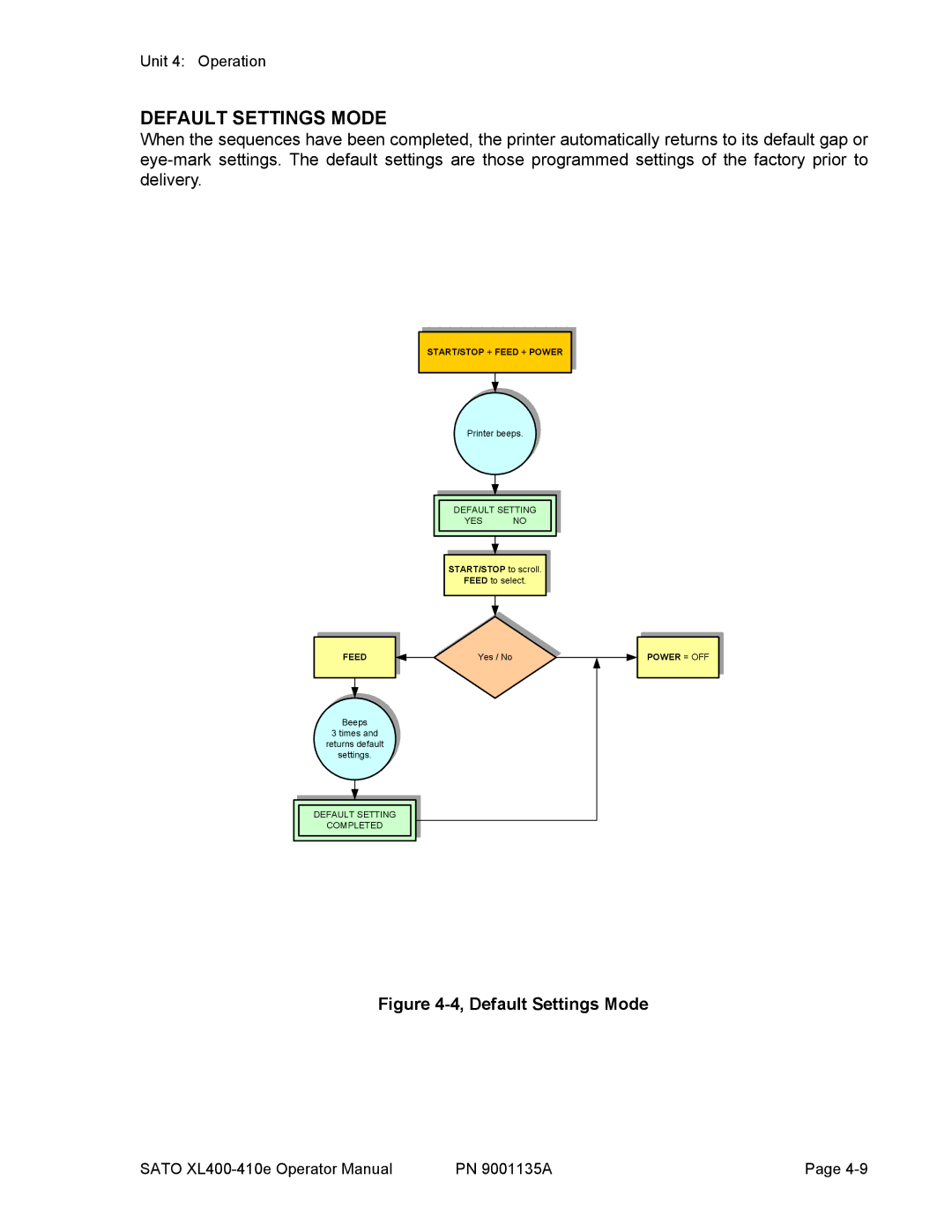
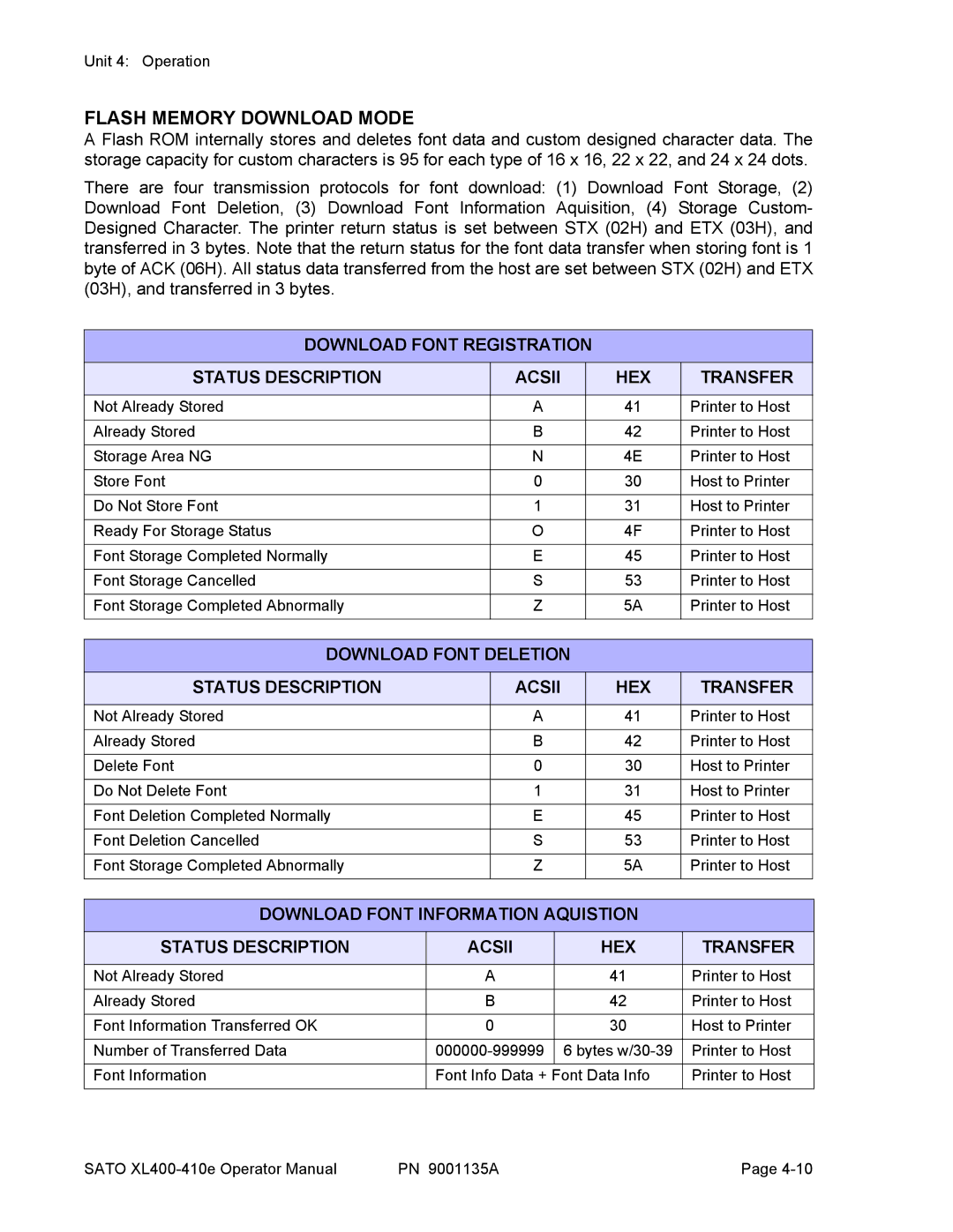
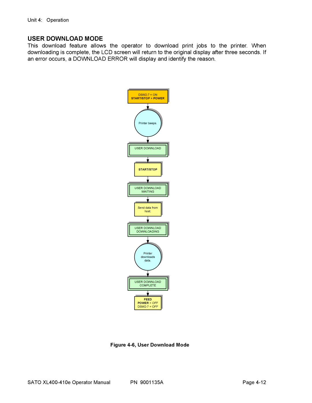
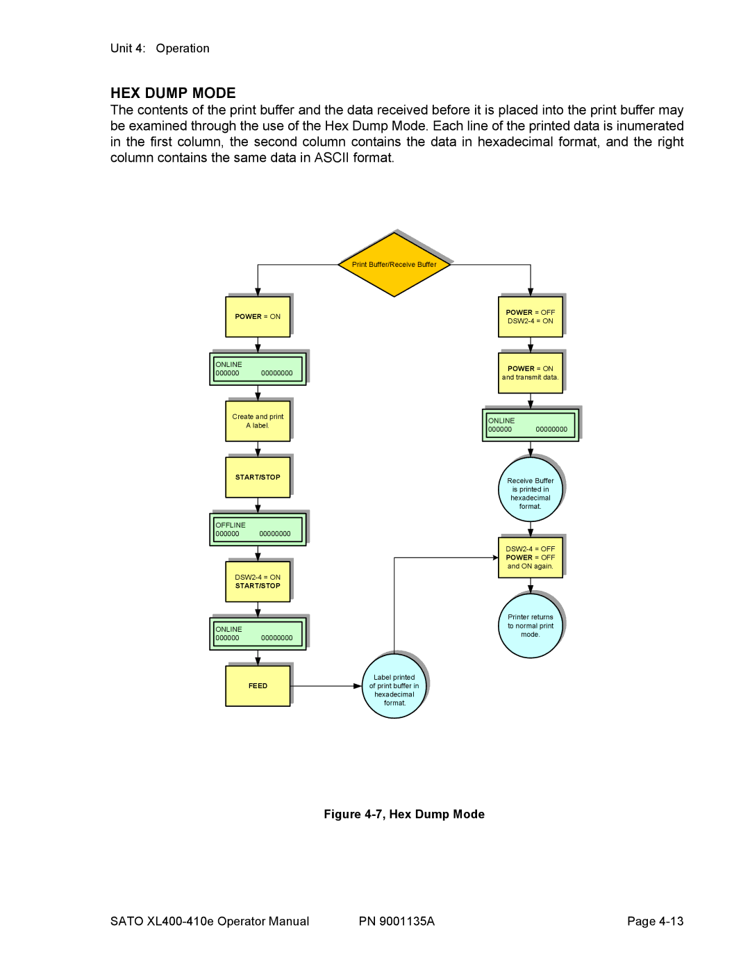
Contents XL400e / XL410e Printers That may appear Table of Contents Operation TroubleshootingAdjustment Procedures MaintenancePN 9001135A Introduction Result in Presonal Injury About this Manual1a, Primary Components General DescriptionButtons & Switches Control Features2b, Control Features Page Technical Data Power Physical CharacteristicsEnvironmental ProcessingCharacter Font Capabilities Regulatory Approvals BAR Code CapabiltiesInterface Modules Installation Unpacking and Parts Identification Unpacking & Parts IdentificationMedia Selection Printer InstallationSite Location 3a, Media Loading Media Loading3b, Media Loading 3d, Media Loading 3f, Media Loading Ribbon Loading4a, Ribbon Loading 4c, Ribbon Loading 4e, Ribbon Loading 4g, Ribbon Loading RS232 Serial Interface RS232C SpecificationsInterface Selection PIN Direction Signal Definition RS232C Serial Interface SignalsCable Requirements DB9 Host Connection DB9 PrinterIEEE1284 Parallel Interface SpecificationsACK Init80211B Wireless Specifications 802.11B WirelessUniversal Serial BUS USB Adapter Local Area Network LAN EthernetACK/NAK Protocol Receive BufferPcmcia Memory Upgrade Accessories InstallationStacker Unit Label Stacker InstallationOperation DIP Switch Panels Printer ConfigurationDSW1 Configuration DSW1 Default SettingsDSW1 Function Descriptions OFFDSW2 Configuration DSW2 Default SettingsConfiguration DSW2 Function DescriptionsFunction Description DSW3 Default SettingsDSW1 Normal Mode Configuration ModesTest Print Mode Test Print ModeAdvanced Mode Advanced ModeDefault Settings Mode Default Settings ModeDownload Font Deletion Status Description Acsii HEX Transfer Flash Memory Download ModeFlash Memory Download Mode User Download Mode User Download ModeHex Dump Mode HEX Dump ModeFeed Card ModeNon-Standard Clear Mode NON-STANDARD Clear Mode10a, Service Mode Test Print Service Mode10b, Service Mode Sensor Level 10c, Service Mode Pitch Offset 10d, Service Mode Cut Offset 10e, Service Mode Backfeed Offset 10f, Service Mode Counter Display Default Settings Mode Normal ModeMenu Description NON-STANDARD Code ClearFlash Memory & User Download Modes Advanced ModeUser Test Print Mode Card ModeService Mode Potentiometer DESCRIPTION/PROCEDURE Operational Adjustments11, Adjustment Panel 14a, Cutter Sensor Positioning Cutter Sensor Positioning15a, Tilting Operator Panel Operator PanelPrinting Powering OFFTest Printing Reloading MediaTroubleshooting LED LCD Message Beep Remedy Error SignalsPrinter Troubleshooting Meandering Media No Printed ImagePrinter Creates a Blank Label Incorrect Label PositioningCHK Troubleshooting Step Interface TroubleshootingLAN Ehternet Interface Multimeter with Test Module Performance TestingMultimeter Alone Test Chart Module Dial Connector PIN FunctionHex Dump Mode Test Print TroubleshootingTest Label Printing Sample Test Label Sensor Locations Sensor LocationsMaintenance Damage Cleaning ProceduresFuse Replacement Replacement ProceduresPrint Head to Prevent Damage to ITS Elements Print Head ReplacementRibbon Roller Replacement Ribbon Roller ReplacementPrint Defects Relative Procedure Adjustment ProceduresPrint Head Balance Adjustment Print Head Balance AdjustmentPrint Head Alignment Print Head AlignmentPressure Roller Alignment Pressure Roller AlignmentPressure Roller Balance Pressure Roller BalanceRibbon Guide Adjustment Ribbon Guide Adjustment10, Ribbon Spindle Tensioning Ribbon Spindle TensioningMultimeter Alone Pitch Sensor Adjustment Label GAP & Center Hole MediaPitch Sensor Adjustment EYE-MARK Media 11, Test Module & Sensor Potentiometers Pitch Sensor Adjustment R-CORNER Media Pitch Sensor Adjustment Side Hole Media Jump Hole Sensor Adjustment VR3 Ribbon Sensor AdjustmentVR1 Cutter Sensor AdjustmentSG / HO VR2

400e, 410e specifications

The SATO 410e and 400e are advanced thermal transfer printers designed for high-performance label printing in a variety of industries, including retail, logistics, and manufacturing. These models are renowned for their reliability, efficiency, and quality output, making them essential tools for businesses that demand precision and durability in their labeling processes.

One of the standout features of the SATO 410e and 400e is their exceptional print quality. They offer a resolution of up to 600 dpi, ensuring that even the most intricate details in barcodes, logos, and text are printed with clarity. This high resolution is crucial for applications that require precision, such as product labeling and inventory management.

The SATO 410e is equipped with an intuitive user interface that simplifies operation. Its LCD display provides real-time information about print status, and its control panel is designed for ease of navigation, reducing the learning curve for new users. On the other hand, the SATO 400e emphasizes compact design without compromising performance, making it an ideal choice for businesses with limited space or needing a mobile labeling solution.

Both models feature a robust set of connectivity options, including USB, Ethernet, and serial interfaces, allowing for seamless integration into existing IT infrastructures. This versatility makes them suitable for various deployment scenarios, whether used standalone or in networked environments.

In terms of speed, the SATO 410e and 400e are engineered to deliver rapid printing capabilities. The 410e can produce labels at a speed of up to 300 mm per second, while the 400e also showcases impressive speed without sacrificing quality. This capability is vital for high-volume printing tasks common in warehousing and distribution operations.

The technology behind these printers includes SATO’s innovative ARCP (Automatic Ribbon Control Path), which optimizes ribbon usage and minimizes waste, contributing to cost-effective printing solutions. Additionally, the SATO 410e and 400e support a wide range of media types and sizes, accommodating various labeling needs from small tags to large shipping labels.

Both models are also designed with durability in mind. They are built to withstand the rigors of industrial environments, ensuring longevity and consistent performance. With features like a strong casing and reliable internal components, users can expect these printers to maintain operational integrity even under demanding conditions.

In conclusion, the SATO 410e and 400e represent the pinnacle of label printing technology, combining high print quality, user-friendly interfaces, efficient connectivity, and robust performance. These printers are perfect for businesses looking to enhance their labeling processes and achieve operational excellence in their respective fields.