Cabletron Systems 2H253-25R manual Connecting Power

Page 37

Installing the Device

3.3.3Connecting Power

NOTE

The two power supplies in the 2H253-25R have automatic voltage sensing that allows connection to power sources ranging from 100–125 Vac, 2.5 A or 200–240 Vac, 1.25 A, 50/60 Hz.

To connect the 2H253-25R to the power sources, proceed as follows:

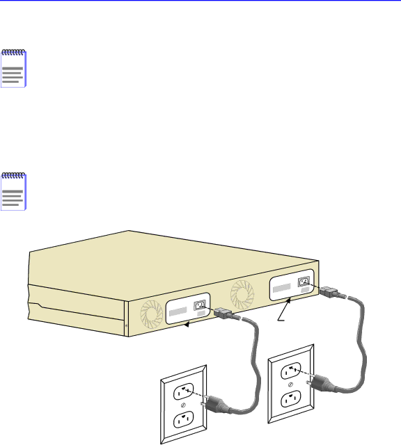
1.Plug each power cord into a grounded wall outlet, see Figure 3-5. To take advantage of the load sharing and redundancy capabilities, each power cord must be plugged into a separate dedicated ac outlet. The POWER LED turns ON (green) and the CPU LED alternates between green and amber during boot up. It takes approximately one minute for the 2H253-25R to boot up.

NOTE

If the power-up sequence is interrupted on this device, or if optional hardware has been installed or removed, this device may run an extended diagnostics sequence that may take up to five minutes to complete.

Redundant

Primary

AC outlets are


on separate circuits

26001-06

Figure 3-5 2H253-25R Rear View

Installation 3-7

Image 37
Contents 2H253-25R SmartSwitch Installation User’s Guide Page Page FCC Notice Cabletron SYSTEMS, INC Program License Agreement Page Page Page Cabletron Systems Limited Program License Agreement Viii Declaration of Conformity Page Contents Troubleshooting Figures Tables About This Guide Using this GuideStructure of this Guide Xvi Related DocumentsDocument Conventions Document ConventionsPage Overview IntroductionAuto-Negotiation ConnectivityRuntime IP Address Discovery Full Duplex Switched EthernetSmartTrunk Broadcast Suppression Remote Monitoring RmonPort/VLAN Redirect Functions Flow Control Rate LimitingSwitching Options Garp Switch Operation12 802.1 Port Priority ManagementOptional HSIMs and VHSIMs Lanview Diagnostic LEDsStandards Compatibility Year 2000 CompliantGetting Help 10BASE-T Network Network Requirements100BASE-TX Network Unpacking the Device InstallationInstalling the Device Installing OptionsGuidelines for Tabletop and Shelf Installations Tabletop or Shelf InstallationGuidelines for the Rackmount Installation Rackmount InstallationAttaching the Strain-Relief Bracket Rack Mounting the 2H253-25R Redundant Primary AC outlets are On separate circuits Connecting PowerConnecting to the Network Straight Cable Connection Completing the Installation Using Lanview TroubleshootingPWR CPU FDX OFF Troubleshooting ChecklistSeries 2E253, 2H252, 2H253, User parameters Position of Mode switch IP address Reset Button Using the Reset ButtonSpecifications Device SpecificationsPhysical Properties Environmental Requirements Electrical SpecificationsINPUT/OUTPUT Ports Regulatory Compliance COM Port Pinout AssignmentsPage Required Tools Optional Installations Mode Switch Bank SettingsRemoving the Chassis Cover Removing the Chassis Cover Figure B-1 Removing the Chassis Cover Switch 6 Forced BootP Setting the Mode SwitchesSimm Upgrade Locating SIMMs Installing the Dram SimmFigure B-4 Installing the Dram Figure B-5 Hsim and Vhsim Connector Locations Installing Optional Hsim or Vhsim Interface ModulesPage Numerics IndexIndex-2