Chapter 1
Introducing the PC-CARD-DIO48
Overview: PC-CARD-DIO48 features
The PC-CARD-DIO48 is a data acquisition and control board for IBM PC compatible computers having PC- CARD/PCMCIA type slots.
PC-CARD-DIO48 features two 82C55 digital I/O chips. The 82C55 chip uses TTL logic.
The digital I/O is organized into two 24-bit groups (24 channels per 82C55). Each 24-bit group is divided into three ports – A, B, and C. Ports A and B are banks of 8 bits. Port C can be configured as two banks of 4 bits or one bank of 8 bits. Each bank is programmable as input or output.
On power up and reset, all I/O bits are set to input mode. All signals pass through a 50-pin high-density connector. The board is completely plug-and-play, with no switches or jumpers to set.
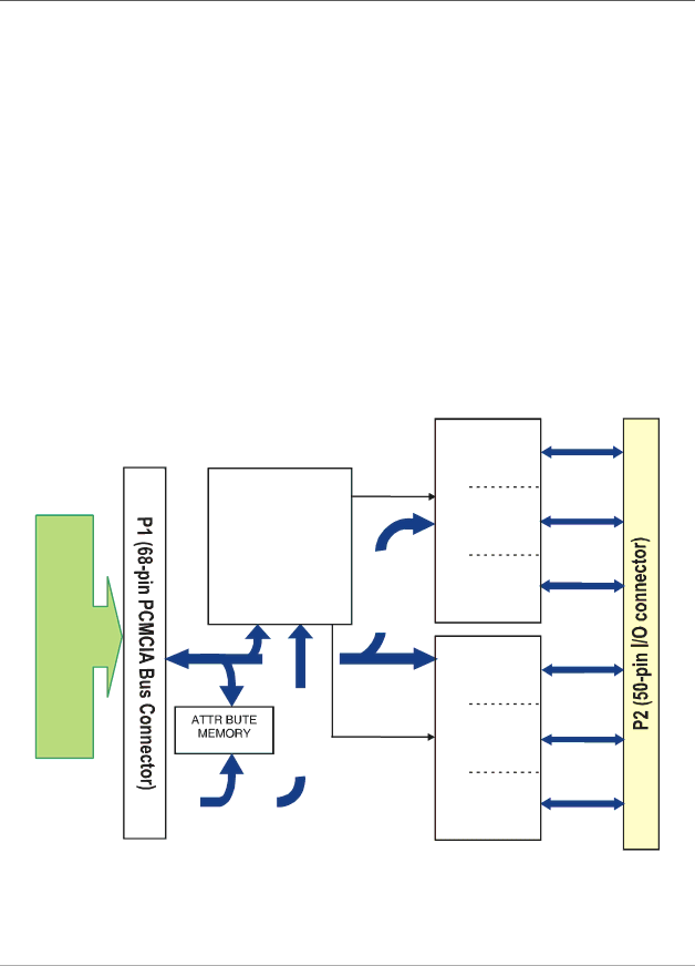
PC-CARD-DIO48 block diagram
PC-CARD-DIO48 functions are illustrated in the block diagram shown here.
| | | | | | | | | | | | | | | | 82C55 |
| | | | | | | | | | | | | | | | | 1st |
Host | | | | | | | | | | | | | | | | Control | 1st |
| | | | | | | | | | | | | | |
| | | | | | Controller | | | | | 1st |
| | | | | | | | | | |
Bus | | | | | | FPGA | | | | | |
| | | | | | | | | |
| | | | | | | | | | | | | | | | |
| | Data Bus | | | | | |
Adaptor | | | | | | | |
| | | | | Control | 2nd |
| | | | | | | | | | | | | | |
| | | | | | | | | | | | | | |
| | | | | | | | | | | | | | |
| | | | | | | | | | | | | | | | |
| | | | | | | | | | | | | | | | |
| | | | | | | | | | | | | | | | | 2nd |
| | | | | | | | | | | | | | | | |
| | | | | | | | | | | | | | | | |
| | | | | | | | | | | | | | | | |
| | | | | | | | | | | | | | | | |
| | | | | | | | | | | | | | | | | 2nd |
| | | | | | | | | | | | | | | | |
| | | | | | | | | | | | | | | | |
| | | | | | | | | | | | | | | | |
| | | Address Bus | | | | | |
| | | | | | | | | | | | | | | | | |
| | | | | | | | | | | | | | | | 82C55 |
| | | | Figure 1. PC-CARD-DIO48 functional block diagram |
A0 (7:0)
B0 (7:0)
C0 (7:0)
A0 (7:0)
B0 (7:0)
C0 (7:0)