Intel® 31244 PCI-X to Serial ATA Controller
Test Methodology
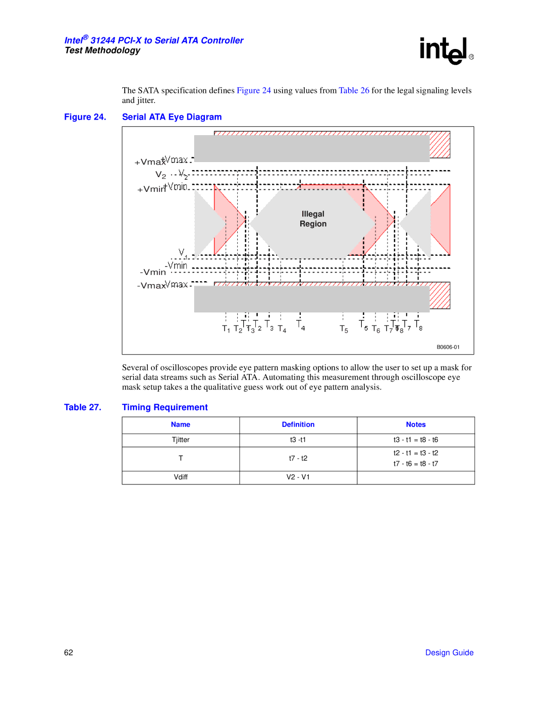
The SATA specification defines Figure 24 using values from Table 26 for the legal signaling levels and jitter.
Figure 24. Serial ATA Eye Diagram
+Vmax
V2
+Vmin
Illegal
Region
T1 T2 T3 | T4 | T5 | T6 T7 T8 |
Several of oscilloscopes provide eye pattern masking options to allow the user to set up a mask for serial data streams such as Serial ATA. Automating this measurement through oscilloscope eye mask setup takes a the qualitative guess work out of eye pattern analysis.
Table 27. | Timing Requirement |
|
|
|
|
| Name | Definition | Notes |
| |
| Tjitter | t3 | t3 - t1 = t8 | - t6 | |
| T | t7 | - t2 | t2 - t1 = t3 | - t2 |
| t7 - t6 = t8 | - t7 | |||
|
|
|
| ||
| Vdiff | V2 | - V1 |
|
|
62 | Design Guide |