Cables and Connectors | 8 |
8.1Cabling
A Serial ATA device is connected to a host through a direct connection or through a cable. For direct connection, the device plug connector, shown as (a) and (b) in Figure 21, is inserted directly into a host receptacle connector, illustrated as (g) in Figure 22. The device plug connector and the host receptacle connector incorporate features that enable the direct connection to be hot pluggable and blind mateable.
Table 25. | Serial ATA Signal Definitions |
| ||
|
|
|
|
|
| Signals |
| Definition | Number of pins |
|
|
|
|
|
| G |
| Ground | 1 |
|
|
|
|
|
| A+/A- |
| Serial ATA port A differential signals | 2 |
|
|
|
|
|
|
| Serial ATA port B differential signals | 2 | |
|
|
|
|
|
| HT+/HT- |
| Host Transmitter differential signals | 2 |
|
|
|
|
|
| HR+/HR- |
| Host Receiver differential signals | 2 |
|
|
|
|
|
| DT+/DT- |
| Device Transmitter Differential Signals | 2 |
|
|
|
|
|
| DR+/DR- |
| Device Receiver Differential Signals | 2 |
|
|
|
|
|
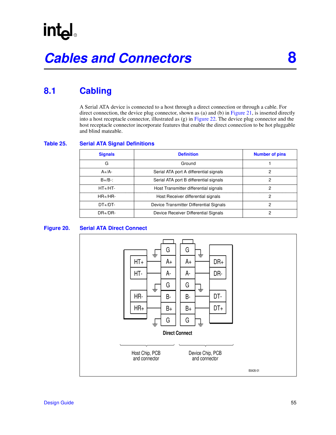
Figure 20. | Serial ATA Direct Connect |
|
| |
HT+
HT-
HR-
HR+
G
A+
A-
G
B-
B+
G
G![]()
A+ A-
G ![]() B- B+
B- B+
G ![]()
DR+
DR-
DT-
DT+
| Direct Connect |
Host Chip, PCB | Device Chip, PCB |
and connector | and connector |
Design Guide | 55 |