Intel® 31244 PCI-X to Serial ATA Controller
Printed Circuit Board (PCB) Methodology
•Jitter tolerance (TJ) must be >= 0.7 UI vs 0.62 UI of spec (@RCV pin)
•Slowest edge rate assumed
•Used only for GD31244 reads
•Read eye was guardbanded by 10 mV to allow for crosstalk
6.2.1Backplane Topologies
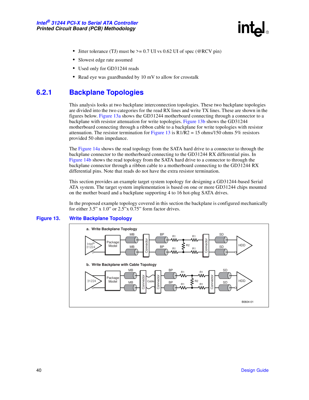
This analysis looks at two backplane interconnection topologies. These two backplane topologies are divided into the two categories for the read RX lines and write TX lines. These are shown in the figures below. Figure 13a shows the GD31244 motherboard connecting through a connector to a backplane with resistor attenuation for write topologies. Figure 13b shows the GD31244 motherboard connecting through a ribbon cable to a backplane for write topologies with resistor attenuation. The resistor termination for Figure 13 is R1/R2 = 15 ohms/150 ohms 5% resistors provided 50 ohm impedance.
The Figure 14a shows the read topology from the SATA hard drive to a connector to through the backplane connector to the motherboard connecting to the GD31244 RX differential pins. In Figure 14b shows the read topology from the SATA hard drive to a connector to through the backplane connector through a ribbon cable to a motherboard connecting to the GD31244 RX differential pins. Note that reads do not have the extra resistor termination.
This section provides an example target system topology for designing a
In the proposed example topology covered in this section the backplane is configured mechanically for either 3.5” x 1.0” or 2.5”x 0.75” form factor drives.
Figure 13. Write Backplane Topology
a. Write Backplane Topology |
|
|
|
|
|
|
|
|
|
| ||
|
| MB |
|
|
| BP | R1 |
|
| R1 |
|
|
|
|
|
| Connector |
|
|
|
|
| Connector | ||
Intel® | Package |
|
|
|
|
|
| R2 |
|
| ||
|
|
|
|
|
|
|
|
|
| |||
Model | MB |
|
|
| BP |
|
|
|
|
| ||
31224 |
|
|
| R1 |
| R1 |
|
| ||||
|
|
|
|
|
|
|
| |||||
|
|
|
|
|
|
|
|
|
|
| ||
b. Write Backplane with Cable Topology |
|
|
|
|
|
|
|
| ||||
|
| MB |
|
|
|
| BP | R1 |
|
| R1 |
|
|
|
| Connector |
| Connector |
|
|
|
| Connector | ||
31224 | Package |
|
|
|
|
|
| R2 |
| |||
|
|
|
|
|
|
|
|
|
| |||
Model | MB |
| Cable |
|
| BP | R1 |
| R1 |
| ||
|
|
|
|
|
|
|
|
| ||||
|
|
|
|
|
|
|
|
|
|
| ||
SD
SD HDD
SD
SD HDD
40 | Design Guide |