Intel® 31244 PCI-X to Serial ATA Controller
Printed Circuit Board (PCB) Methodology
6.1Intel® 31244
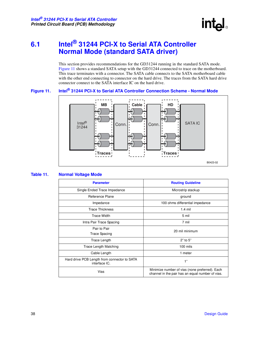
This section provides recommendations for the GD31244 running in the standard SATA mode. Figure 11 shows a standard SATA setup with the GD31244 connected to trace on the motherboard. This trace terminates with a connector. The SATA cable connects to the SATA motherboard cable with the other end connecting to connector on the hard drive. The traces from the SATA hard drive connector connect to the SATA interface IC on the hard drive.
Figure 11. Intel® 31244 PCI-X to Serial ATA Controller Connection Scheme - Normal Mode
Intel®
31244
MB
Traces
Conn. |
Cable
Conn. |
HD
Traces
SATA IC
Table 11. | Normal Voltage Mode |
|
|
|
|
| Parameter | Routing Guideline |
|
|
|
| Single Ended Trace Impedance | Microstrip stackup |
|
|
|
| Reference Plane | ground |
|
|
|
| Impedance | 100 ohms differential impedance |
|
|
|
| Trace Thickness | 1.4 mil |
|
|
|
| Trace Width | 5 mil |
|
|
|
| Intra Pair Trace Spacing | 7 mil |
|
|
|
| Pair to Pair | 20 mil minimum |
| Trace Spacing | |
|
| |
|
|
|
| Trace Length | 2” to 5” |
|
|
|
| Trace Length Matching | 100 mils |
|
|
|
| Cable Length | 1 meter |
|
|
|
| Hard drive PCB Length from connector to SATA | 1” |
| interface IC. | |
|
| |
|
|
|
| Vias | Minimize number of vias (none preferred). Each |
| channel in the pair has an equal number of vias. | |
|
| |
|
|
|
38 | Design Guide |