10.1Extended Voltage Mode
Figure 25, Figure 26, Table 28 and Table 29 describe the extended voltage mode eye diagrams for the modified receiver and driver. These eye diagrams needed to be modified from the original SATA specification to allow for the higher voltage parameters required for a backplane design.
Note: The material in this section is preliminary.
10.1.1Extended Voltage Mode Receiver Model
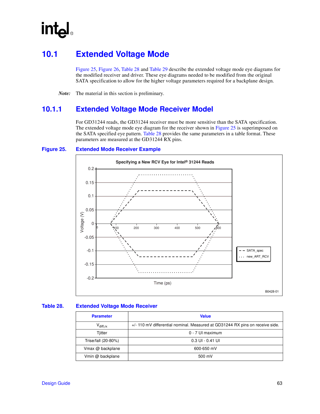
For GD31244 reads, the GD31244 receiver must be more sensitive than the SATA specification. The extended voltage mode eye diagram for the receiver shown in Figure 25 is superimposed on the SATA specified eye pattern. Table 28 provides the same parameters in a table format. These parameters are measured at the GD31244 RX pins.
Figure 25. Extended Mode Receiver Example
Specifying a New RCV Eye for Intel® 31244 Reads
| 0.2 |
|
|
|
|
|
|
| 0.15 |
|
|
|
|
|
|
| 0.1 |
|
|
|
|
|
|
(V) | 0.05 |
|
|
|
|
|
|
|
|
|
|
|
|
| |
Voltage | 0 |
|
|
|
|
|
|
0 | 100 | 200 | 300 | 400 | 500 | 600 | |
|
|
|
|
|
|
| |
|
|
|
|
|
|
| |
|
|
|
|
|
|
| |
|
|
|
|
|
|
| |
|
|
|
|
|
|
|
Time (ps)
SATA_spec
new_ART_RCV
|
|
| |
|
|
|
|
Table 28. | Extended Voltage Mode Receiver |
| |
|
|
|
|
| Parameter |
| Value |
|
|
| |
| Vdiff,rx | +/- 110 mV differential nominal. Measured at GD31244 RX pins on receive side. | |
| Tjitter | 0 - 7 | UI maximum |
|
|
|
|
| Trise/fall | 0.3 | UI - 0.41 UI |
|
|
| |
| Vmax @ backplane | ||
|
|
|
|
| Vmin @ backplane |
| 500 mV |
|
|
|
|
Design Guide | 63 |