Test Methodology | 10 |
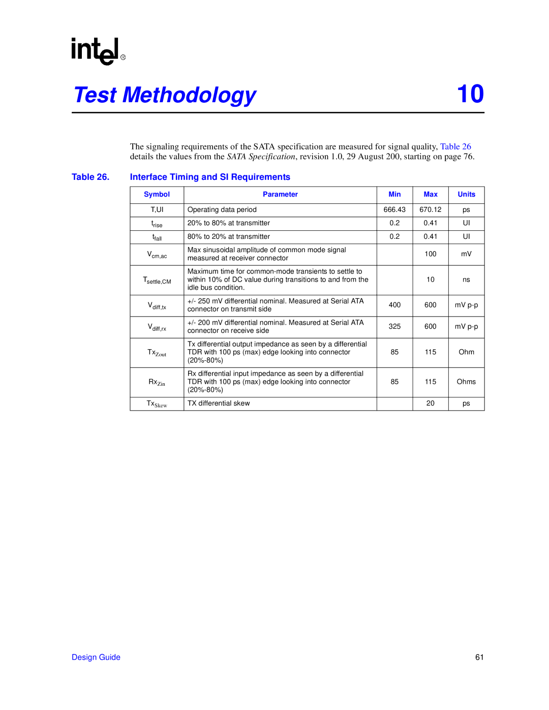
The signaling requirements of the SATA specification are measured for signal quality, Table 26 details the values from the SATA Specification, revision 1.0, 29 August 200, starting on page 76.
Table 26. | Interface Timing and SI Requirements |
|
|
| |
|
|
|
|
|
|
| Symbol | Parameter | Min | Max | Units |
|
|
|
|
|
|
| T,UI | Operating data period | 666.43 | 670.12 | ps |
|
|
|
|
|
|
| trise | 20% to 80% at transmitter | 0.2 | 0.41 | UI |
| tfall | 80% to 20% at transmitter | 0.2 | 0.41 | UI |
| Vcm,ac | Max sinusoidal amplitude of common mode signal |
| 100 | mV |
| measured at receiver connector |
| |||
|
| Maximum time for |
|
|
|
| Tsettle,CM | within 10% of DC value during transitions to and from the |
| 10 | ns |
|
| idle bus condition. |
|
|
|
|
|
|
|
|
|
| Vdiff,tx | +/- 250 mV differential nominal. Measured at Serial ATA | 400 | 600 | mV |
| connector on transmit side | ||||
| Vdiff,rx | +/- 200 mV differential nominal. Measured at Serial ATA | 325 | 600 | mV |
| connector on receive side | ||||
| TxZout | Tx differential output impedance as seen by a differential |
|
|
|
| TDR with 100 ps (max) edge looking into connector | 85 | 115 | Ohm | |
|
|
|
|
| |
|
|
|
|
|
|
|
| Rx differential input impedance as seen by a differential |
|
|
|
| RxZin | TDR with 100 ps (max) edge looking into connector | 85 | 115 | Ohms |
|
|
|
|
| |
|
|
|
|
|
|
| TxSkew | TX differential skew |
| 20 | ps |
Design Guide | 61 |