Intel® 31244 PCI-X to Serial ATA Controller
7.4.5Embedded Intel® 31244
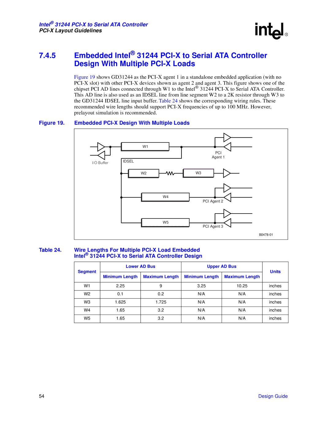
Figure 19 shows GD31244 as the PCI-X agent 1 in a standalone embedded application (with no PCI-X slot) with other PCI-X devices shown as agent 2 and agent 3. This figure shows one of the chipset PCI AD lines connected through W1 to the Intel® 31244 PCI-X to Serial ATA Controller. This AD line is also used as an IDSEL line from line segment W2 to a 2K resistor through W3 to the GD31244 IDSEL line input buffer. Table 24 shows the corresponding wiring rules. These recommended wire lengths should support PCI-X frequencies of up to 100 MHz. However, prelayout simulation is recommended.
Figure 19. Embedded PCI-X Design With Multiple Loads
| W1 |
|
|
| PCI |
| IDSEL | Agent 1 |
I/O Buffer |
| |
|
| |
| W2 | W3 |
|
| W4 |
|
| PCI Agent 2 |
|
| W5 |
|
| PCI Agent 3 |
|
|
Table 24. Wire Lengths For Multiple
Intel® 31244
| Lower AD Bus | Upper AD Bus |
| ||
Segment |
|
|
|
| Units |
| Minimum Length | Maximum Length | Minimum Length | Maximum Length |
|
|
|
|
|
|
|
W1 | 2.25 | 9 | 3.25 | 10.25 | inches |
|
|
|
|
|
|
W2 | 0.1 | 0.2 | N/A | N/A | inches |
|
|
|
|
|
|
W3 | 1.625 | 1.725 | N/A | N/A | inches |
|
|
|
|
|
|
W4 | 1.65 | 3.2 | N/A | N/A | inches |
|
|
|
|
|
|
W5 | 1.65 | 3.2 | N/A | N/A | inches |
|
|
|
|
|
|
54 | Design Guide |
