Intel® 31244 PCI-X to Serial ATA Controller
Intel® 31244
5.4.3LED Interface
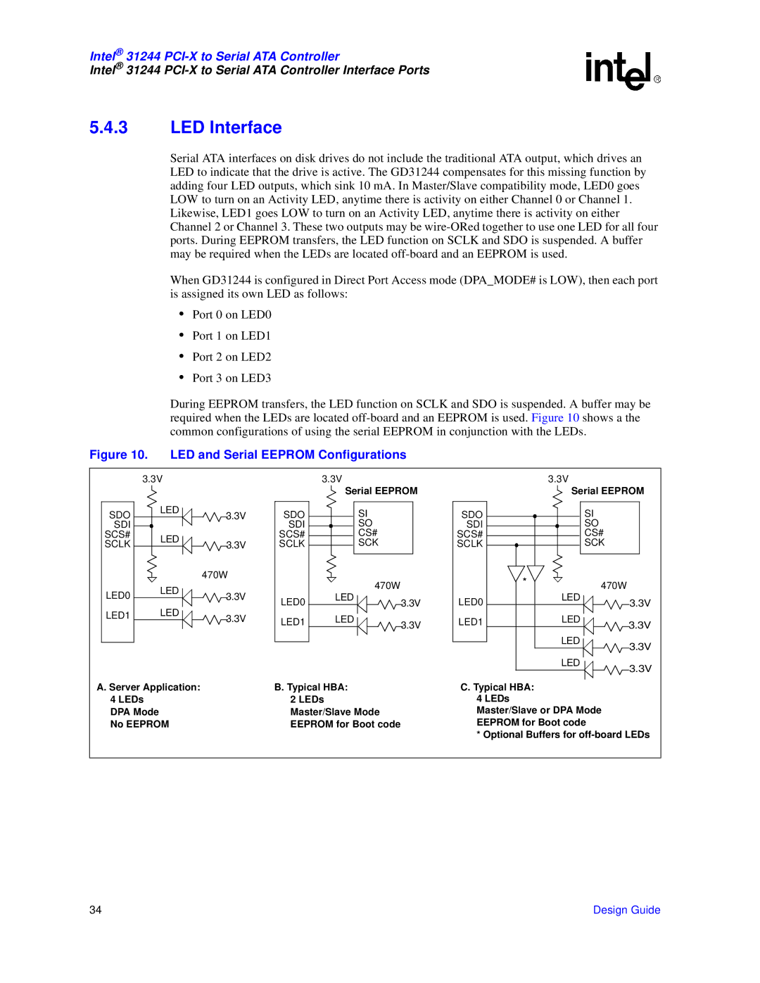
Serial ATA interfaces on disk drives do not include the traditional ATA output, which drives an LED to indicate that the drive is active. The GD31244 compensates for this missing function by adding four LED outputs, which sink 10 mA. In Master/Slave compatibility mode, LED0 goes LOW to turn on an Activity LED, anytime there is activity on either Channel 0 or Channel 1. Likewise, LED1 goes LOW to turn on an Activity LED, anytime there is activity on either Channel 2 or Channel 3. These two outputs may be
When GD31244 is configured in Direct Port Access mode (DPA_MODE# is LOW), then each port is assigned its own LED as follows:
•Port 0 on LED0
•Port 1 on LED1
•Port 2 on LED2
•Port 3 on LED3
During EEPROM transfers, the LED function on SCLK and SDO is suspended. A buffer may be required when the LEDs are located
Figure 10. LED and Serial EEPROM Configurations
3.3V |
|
| 3.3V |
|
| 3.3V |
| |
|
|
|
| Serial EEPROM |
| Serial EEPROM | ||
SDO | LED | 3.3V | SDO | SI |
| SDO | SI |
|
|
|
| ||||||
SDI |
|
| SDI | SO |
| SDI | SO |
|
SCS# | LED |
| SCS# | CS# |
| SCS# | CS# |
|
SCLK | 3.3V | SCLK | SCK |
| SCLK | SCK |
| |
|
|
| ||||||
|
| 470W |
| 470W |
| * | 470W |
|
| LED |
|
|
|
| |||
LED0 | 3.3V |
|
|
|
| |||
| LED |
|
| LED |
| |||
| LED0 | 3.3V | LED0 | 3.3V | ||||
| LED |
|
|
| ||||
LED1 | 3.3V | LED1 | LED | 3.3V | LED1 | LED | 3.3V | |
|
| |||||||
|
|
|
|
|
|
| ||
|
|
|
|
|
|
| LED | 3.3V |
|
|
|
|
|
|
|
| |
|
|
|
|
|
|
| LED | 3.3V |
|
|
|
|
|
|
|
| |
A. Server Application: |
| B. Typical HBA: |
| C. Typical HBA: |
|
| ||
4 LEDs |
|
| 2 LEDs |
| 4 LEDs |
|
| |
DPA Mode |
|
| Master/Slave Mode |
| Master/Slave or DPA Mode |
| ||
No EEPROM |
| EEPROM for Boot code |
| EEPROM for Boot code |
| |||
|
|
|
|
|
| * Optional Buffers for | ||
34 | Design Guide |