Manuals
/
Samsung
/
Kitchen Appliance
/
Refrigerator
Samsung
RM255BASB, RM255BABB
manual
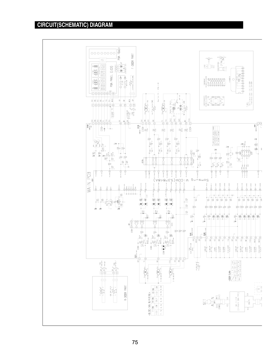
Circuitschematic Diagram
Models:
RM255BABB
RM255BASB
1
76
88
88
Download
88 pages
34.33 Kb
73
74
75
76
77
78
79
80
Specs
Wiring Diagram
Alarm Function
Error
Symbols
Replace connector and wire
Self-Diagnostics Function
Disassembly and Reassembly
Option Setting Function
Temperature Control Operation
Page 76
Image 76
CIRCUIT(SCHEMATIC) DIAGRAM
75
Page 75
Page 77
Page 76
Image 76
Page 75
Page 77
Contents
RM255BARB RM255BASB RM255BABB
Authorized Training Center Campuses
Important Safety Notice
Contents
Precautionssafety Warnings
Symbols
Forbidden
Product Specifications
This operation instruction covers various models
Manual
RM25
Model Specification
After packing 386lbs
Electric Parts Specification
Sensor
Specifications Model Dispenser Home Bar
Electric Components
Items
Running
Photograph
Optional Material Specifications
Part Code
Operating Instructions & Installation
Temperature Control Operation
Digital Panel
Power Freeze and Power cool Operation
Power Freeze Operation
Power cool Operation
By in inside function irrespective of current setting
At Initial Power On
Lock Function
Able to operate on front panel
Cube / Crushed / ICE OFF Selection Function
Machine Room F-Fan Motor Delay Function
Water Dispenser Function
Light Operation
Load Operation Condition
Initial Operation
Reverse rotation CCW Forward rotation CW Ice extraction
Horizontal position Interval about 880ms
Maximum torsion point
Water Supply Function
Ice-Making Function
Ice Extraction Function
Water Supply Time
Bold numerals indicate relevant ice tray steps
Horizontality operation
Defrosting Function
Defrosting period is fixed to 8 hours
Arctic Zone
53.6 62.6
Arctic Select Zone Function
Function
Operation
Fresh Select Zone Function
Function Operation Specification
Temp .8 ~ 44.6 of the Fridge compartment
Test KEY
Operation start
Forced Defrosting Function
For the R compartment
Alarm Function
Communication Error Display Function
When water supply is finished, in the ice maker test mode
Display Function at Panel
Operating Instructions & Installation
Self-Diagnostics Function
Self-Diagnostics Checklist
BAD Item Trouble Status
Error
Defrosting
Sensor of R
CR Sensor
CF-FAN Error
CR-FAN Error
On Error
Trouble
Load Condition Display Function
Load Mode Checklist Load Item Load Status
Relevant displays about load status is as follows
Changing to Optional Mode
Option Setting Function
KEY Function
Value Item
Temperature Change Table for the Freezer Compartment
Change for freezer compartment
Temperature Change Table for the Refrigerator Compartment
KEY
CR Room Temperature Shift Function
Case of basic model, the following items cannot be set
Maker For Ice Maker
Flow sensor
Disassembly and Reassembly
Removing the Front Leg Cover
Door Assy
Removing the Freezer Door
Removing the Refrigerator Door
Remove two screws holding it to
Open the Fresh Select Zone Door
Liner on the right side of the rail To separate it
Reattaching the Freezer Door
Reattaching the Refrigerator Door
Levelling
Open the Arctic Select Zone Door
Zone
Water line must be connected to drinkable water only
Do not overtighten the compression Note nut
Close the filter cartridge cover
Door Sub Parts
Control Panel
Door Handle
Door Gasket
Refrigerator Door Light Switch
Refrigerator Light
Tempered Glass Shelf
Plastic Drawers in the Refrigerator
Freezer Door Light Switch
Freezer Compartments
Door Bin in Freezer
Plastic Drawer in Freezer
Tighten the screws 2 of the ice maker support
Ice Dispenser Ice Maker
Freezer Light
Auger Motor Case
Upper Ductwork
Partition in the Freezer
Screws Pull the upper part of the evaporator cover slightly
Evaporator Fan Motor
Evaporator in Freezer
Freezer Thermistor
Thermistor cover Screw
Ice-Maker Thermistor
Water Tank
Evaporator cover in the Refrigerator
Evaporator Fan Motor in Refrigerator
Evaporator in Fridge
Refrigerator Thermistor
Ductwork Thermistor Thermistor cover
Fresh /Arctic Select ZoneTM Thermistor
Upper Ductwork
Machine Compartment Electric Box
PCB-MAIN Assy
Sub-condenser
Water Solenoids
Removing the Arctic Select Zone Accessories
If power is not on
Start
Normal
Check at the Smps PBA Check Main PCB connection
Exchange and repair COMP. Assembly
Check connector for Contact failure
If the compressor doesn’t work normally
Reference
Perform forced defrosting for F R room one at a time
If the ambient temperature sensor has trouble
How To Check Temperature Sensing in the manual
If there is a trouble with self-diagnosissensor failure
Check the soldering on the main PCB for Shorts & breaks
Alarm Sounds continuouslyrelated to the buzzer
If Ding-Dong sounds continuously Start
If Beep sounds continuously Start
Gasket, food etc
If the buzzer doesn’t sound
Main PCB is normal, buzzer is Normal
Buzzer is broken - replace it
Replace buzzer or panel PCB
If the panel PCB is not working normally
Where the Panel PCB key isn’t selected
It is a care
If fan motor doesn’t working normaly
Door S/W
Door Open 0V DC
Condition
These signals will be inputted into Micom
Door Open DC
If Ice Cubed or/and Ice Crushed dont work normally
If Indoor Lamp of Freezer/Refrigerator doesn’t light
Replace Inside lamp Replace or troubleshoot Door S/W
If Water Drawer doesnt work normally Preliminary Check
Replace connector Wire and switch
Replace connector and wire
If Dispenser LED Lamp doesnt light
Failure of panel PCB itself
Wiring Diagram
Connector Arrangement Main Board
Circuitschematic Diagram
Conn Ector Arrangement SMP S Board
Power BUS
A voltage proportional to
98.9
93.7 40.0 88.9 38.2 84.2 36.4 79.8 34.6 75.7 32.8 71.8
68.2
64.7
#18 GND0.8V
IC75 Input IC75 Output FAN
107
Motor Drive Circuit Descriptions
Principle of Operation
Comparison in HIGH/LOW Speed
Remarks
XAA
13-2 Q & a Problem Possible Causes What To Do
Reference Information
Problem Possible Causes What To Do
Small or hollow cubes
Compressor Sub-condenser Hot Pipe Dryer Step valve
Additional Information
Suction Pipe
Freezer Refrigerator
Top
Page
Image
Contents