CIRCUIT DESCRIPTIONS
12-9. INTERNAL REFRIGERATOR FAN MOTOR OPERATING CIRCUIT
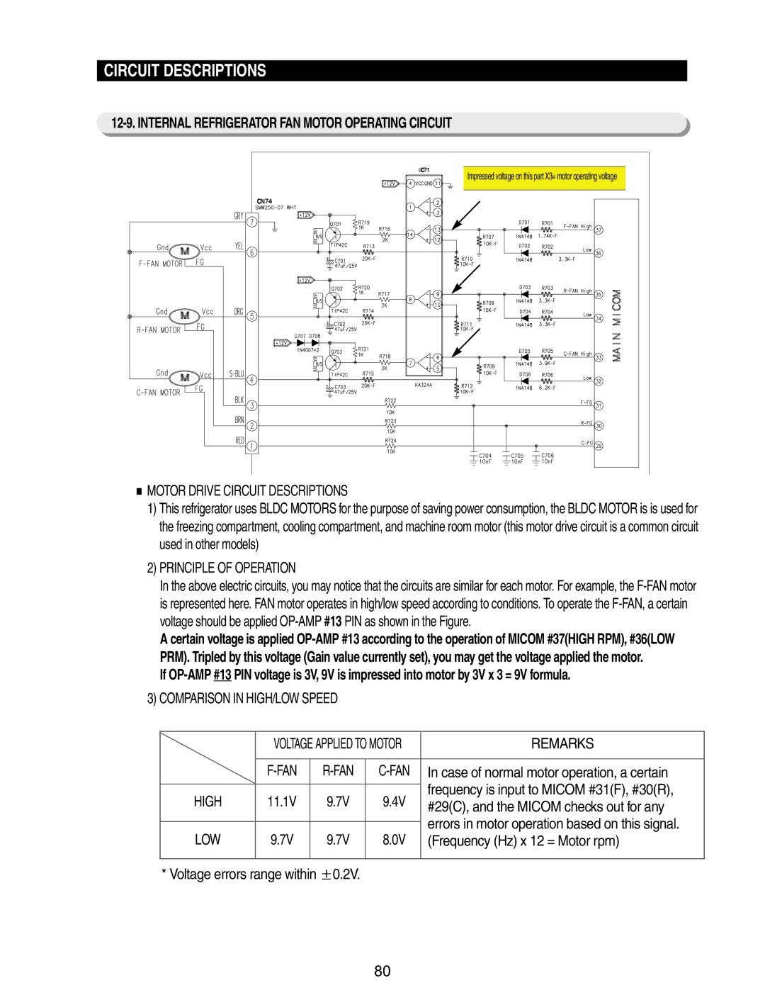
Impressed voltage on this part X3= motor operating voltage
MOTOR DRIVE CIRCUIT DESCRIPTIONS
1)This refrigerator uses BLDC MOTORS for the purpose of saving power consumption, the BLDC MOTOR is is used for the freezing compartment, cooling compartment, and machine room motor (this motor drive circuit is a common circuit used in other models)
2)PRINCIPLE OF OPERATION
In the above electric circuits, you may notice that the circuits are similar for each motor. For example, the
A certain voltage is applied
If
3)COMPARISON IN HIGH/LOW SPEED
| VOLTAGE APPLIED TO MOTOR | REMARKS | |||
|
|
|
|
| |
|
| In case of normal motor operation, a certain | |||
HIGH | 11.1V |
| 9.7V | 9.4V | frequency is input to MICOM #31(F), #30(R), |
| #29(C), and the MICOM checks out for any | ||||
|
|
|
|
| |
|
|
|
|
| errors in motor operation based on this signal. |
LOW | 9.7V |
| 9.7V | 8.0V | |
| (Frequency (Hz) x 12 = Motor rpm) | ||||
|
|
|
|
|
|
* Voltage errors range within | 0.2V. |
|
| ||
80
