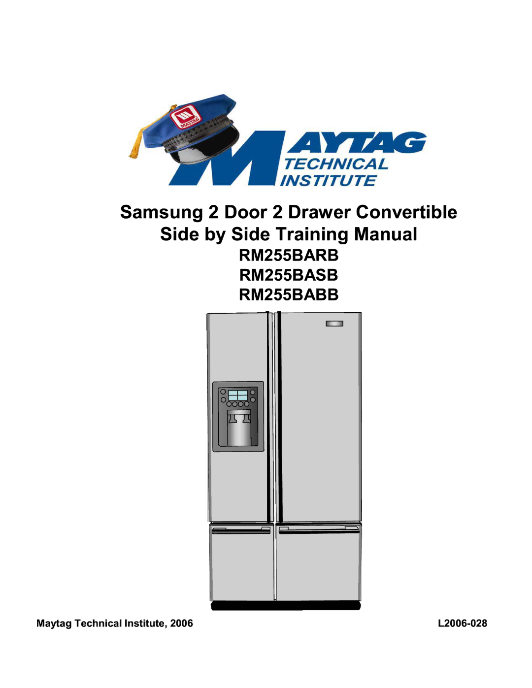
Samsung 2 Door 2 Drawer Convertible
Side by Side Training Manual
Maytag Technical Institute, 2006
L2006-028