1.0INTRODUCTION
The SmartSwitch™ is an automatic transfer switch designed to provide fast automatic transfers between two independent, synchronous AC power sources to provide continuity of AC power to critical equipment, such as information technology equipment, despite irregularities in either of the two AC input power sources. The transfer is accomplished with sense and transfer times of less than 6 milliseconds. The SmartSwitch is available in a 2, 3, or 4 pole configurations, with ampacities of 13, 15, 20, 25, 30, 50, or 60 amps, in a floor, wall, or rack mount packages. Inputs may be hardwired or plug connected to the two input branch circuits. Outputs may be receptacles or hardwired connected to the load equipment.
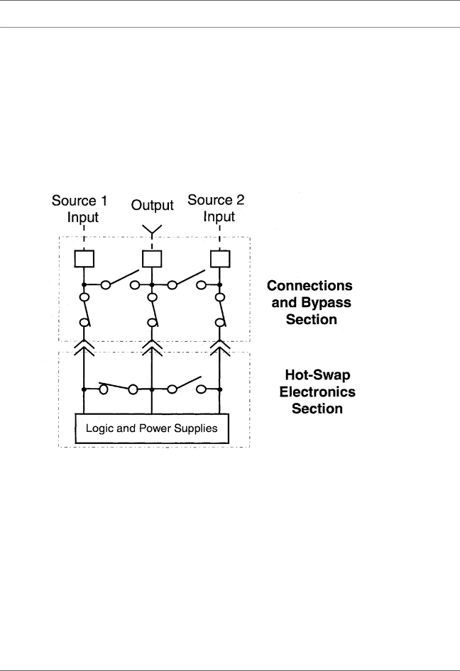
The SmartSwitch consists of two modules, a fixed module containing the input and output connec- tions and bypass switch with a compartment that holds the
Figure 1 Typical SmartSwitch One-Line Diagram
1.1Specifications
1.1.1General Specifications
•Manual and Automatic Transfers.
•Sense and Transfer Time: Less than 6 milliseconds.
•
•Selectable Preferred Source.
•Selectable Auto/Manual Retransfer.
•Retransfer Time Delay: 1 to 60 seconds adjustable.
•
•Output Overload Transfer Inhibit: 1 to 10 times full load current adjustable.
•Programmable Switch Self Test.
•Convection Cooling.
2 Introduction