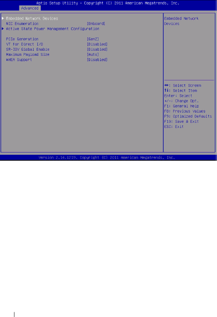
Dell C5220 owner manual Advanced\PCI Configuration, Onboard

Page 34

PCI Configuration

Menu Fields

Settings

Comments


Advanced\PCI Configuration


Embedded Network


Embedded Network

Devices


Devices.


NIC Enumeration

Onboard*

Change the sequence of


Add-in

NIC OPROM


initialization.


NOTE: Function supported


after BIOS 2.0.X.


Active State Power


Active State Power

Management


Management

Configuration


Configuration.


34

Using the System Setup Program

Image 34
Contents Dell PowerEdge C5220 Systems Regulatory Model B04S Important Information Page Contents 111 119About Your System Front-Panel Features and Indicators FeaturesFeature Description Indicators Feature Status DescriptionFeature Status Description About Your System About Your System About Your System About Your System About Your System Using the System Setup Program Start MenuEnable/Disable Console Redirection Bios Setup Options at BootConsole Redirection Configuring Special Keys Key Ansi Escape Sequence Other SequencesGeneral Help Server Platform Setup Utility Screens ConventionsMain Menu MainDisplays the processor type Advanced Menu AdvancedPower Management Advanced\CPU Configuration CPU ConfigurationState Enabled DisabledAll Prefetch Configuration Advanced\CPU Configuration\Prefetch Configuration EnableDisable Memory ConfigurationAdvanced\Memory Configuration AutoSata Configuration Advanced\SATA ConfigurationDrive Port Mapping of Cougar Point Sata Controllers Advanced\PCI Configuration PCI ConfigurationOnboard Gen2 Enabled with PXE Advanced\PCI Configuration\Embedded Network DevicesEmbedded Network Devices Active State Power Management Configuration Enabled without PXEL0s & L1 PCI Slot Configuration Advanced\PCI Configuration\PCI Slot ConfigurationUSB Configuration Advanced\USB ConfigurationUSB Port with BMC Disabled Server Management Server ManagementMenu Fields Settings Comments Set BMC LAN Configuration Server Management/BMC Network ConfigurationIP Address Xxx.xxx.xxx.xxx Enter IP address Form Remote Access Configuration Server/Remote Access ConfigurationPost View System Event Log Using the System Setup Program Boot Menu BootBios Security Menu SecuritySave and Exit Save & ExitCD/DVD ROM Error Messages Post Error HandlingStatus Codes Status Codes Status Code Description Command Line Interfaces for Setup options Safety Measures Recommended ToolsInside the System Inside the SystemSled Configuration PowerEdge C5220 8-Sled SKUSleds Removing a SledInstalling a Sled Memory Modules Supported Dimm ConfigurationDimm Population Rules Supported Memory Supported MemoryDDR3 ECC VLP Removing and Installing a Memory Module Removing a Memory ModuleReplacing a Memory Module Hard Drives Removing a 2.5-inch Hard DriveHDD2 HDD3 Installing a 2.5-inch Hard Drive Removing a 3.5-inch Hard Drive Remove the hard drive cables from the cable clips Installing a 3.5-inch Hard Drive Insert the hard drive cables into the cable clips Hard Drive Boards Removing a 2.5-inch Hard Drive BoardInstalling a 2.5-inch Hard Drive Board Removing a 3.5-inch Hard Drive BoardInstalling a 3.5-inch Hard Drive Board Heat Sinks Removing a Heat Sink/ShroudRemoving a heat sink/shroud Installing a Heat Sink/Shroud Installing a heat sink/shroudFinal installed view of a heat sink/shroud Removing a Heat Sink Removing a heat sinkInstalling a Heat Sink 10. Installing a heat sinkProcessors Removing a ProcessorInstalling a Processor Mezzanine Cards Installing a 1 GbE and 10 GbE Mezzanine CardReplacing a Mezzanine Card Optional 11. Installing a Linking Board in a Mezzanine Card 13. Securing a Mezzanine Assembly Removing a 1 GbE and 10 GbE Mezzanine CardRemove the card from the assembly Installing a SAS Mezzanine Card with 2.5 HDD 16. Inserting a Linking Board in a SAS Mezzanine Card17. Installing a SAS Mezzanine Assembly in a Sled Routing the 2.5 SAS Mezzanine Cables Removing a SAS Mezzanine Card with 2.5 HDD19. Removing a SAS Mezzanine Assembly in a Sled Installing a SAS Mezzanine Card with 3.5 HDD 20. Removing a SAS Mezzanine Card21. Inserting a Linking Board on a 3.5 SAS Mezzanine Card Removing a SAS Mezzanine Card with 3.5 HDD Routing the 3.5 SAS Mezzanine CablesSAS Cable Identification SAS Cable 24 .5 SAS CableServer Boot Issues Troubleshooting SequenceSystem Does Not Boot After Initial Installation 100 Product Family101 System Does Not Boot After Configuration Changes 102Installation Problems 103BMC Firmware Update Update UtilitiesTroubleshooting External Connections Firmware Recovery Utility-SOCFLASH Utility105 Updates Through TFTP/HTTP/FTP 106107 108 Firmware Update Utility-AMI Flash Utility Bios System UpdateBios Recovery Mode Bios Recovery Flow110 System Board Jumpers and Connectors 111112 JP5Inch Hard Drive Board Connectors 113Sled Backplane Front Connectors Backplane Connectors114 Sled Backplane Back Connectors 1156shows the 12-sled backplane front connectors 116Power Distribution Board Connectors 117PDB Power and SMBus Connectors 118Contacting Dell 119120 Index 121122 123 124
Related manuals
Manual 60 pages 55.3 Kb