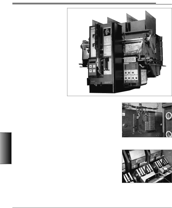
Siemens 480V manual LV Power Circuit Breakers, Typical Breaker Features, Circuit Breaker Racking

Page 6

480V Metal-Enclosed Switchgear

LV Power Circuit Breakers

General

The Siemens RL series circuit breakers are designed for up to 600 volt service with current carrying capacities of up to 5000 amperes and interrupting capacities of up to 130,000 amperes unfused or 200,000 amperes fused.

These compact, fast operating circuit breakers incorporate a stored energy closing mechanism, either manually or electrically charged, for fast, positive closing.

A quick-make closing mechanism releas- es the stored energy for high speed clos- ing of the primary contacts. This positive, controlled closing prevents unnecessary arcing between the movable and station- ary breaker contacts and thus lengthens contact and breaker life.

Manual tripping is performed with the push lever on the front of the breaker. Up to three padlocks can be used to lock the breaker contacts in the open position.

Typical Breaker Features

J

Arc Quenchers

J Main and Arcing Contact Structures

J

Inductive Tripping Sensors

J

Control Wiring

J

Interlocks

Type RL Circuit Breaker With Static Trip III Trip Unit And Optional Breaker Display Unit (BDU)

4

480V Enclosed-MetalSwitchgear

J

Position Indicators

J

Interpole Barriers

J

Mechanical Trip Bar

J

Auxiliary Switches (option)

Each circuit breaker is a complete 3-pole, single-throw element that is mechanically and electrically trip-free, with a Static Trip III overcurrent trip unit.

Tables 4.16 and 4.17 show circuit breaker operating and control data.

Circuit Breaker Racking

Racking is accomplished by turning a racking screw on the front of the breaker and may be done with the compartment door open or closed. The racking screw turns U-shaped brackets on each side of the breaker which rack the breaker frame in or out of the compartment.

As the racking screw is turned counter- clockwise, the breaker frame moves out of the compartment and disconnects the primary contacts, followed by the sec- ondary contacts. With only the secondary contacts connected (test position), the breaker may be closed and opened for testing without energizing the load. An indicator located on the front of the breaker identifies the position of the breaker in the compartment.

Primary Disconnects

Primary current is applied to the circuit breaker through silver plated disconnects. The stationary contacts are mounted through solid Pyro-Shield insulation sheets in the back of the compartments. The movable contacts are mounted on the back of the breaker. Stainless steel springs provide pressure to the finger contacts in the connected position. Low contact resistance is maintained by these self-aligning contacts. The primary con- tacts are positioned so that current can flow only in the connected position. In the test position the contacts are separat- ed a safe distance.

Secondary Disconnects

Secondary circuits are connected to the circuit breaker through silver-plated, slide- type contacts which are located below the arc quenching area to avoid contami- nation from arc product gases. The posi- tion of these contacts is visible with the panel door open. The stationary contacts are silver-plated copper strips mounted on a Pyro-Shield molded base. The con- tacts are recessed to guide the movable, self-aligning contacts and to prevent acci- dental short circuiting. Secondary connec- tions are made automatically in both the connected and test positions.

Secondary Disconnects in Cell

Left = Communications

Right = Breaker Control

Main and Arcing Contacts — Similar Design for all Ratings

54

Siemens Electrical Products and Systems

CSI Section 16470

Specification Guide


Image 6
Contents Utility and Co-generation Facilities LV switchgear is typically installedGeneral Industry Standards480V Metal-Enclosed Switchgear General Assembly ConstructionConstruction Details FinishInsulation Control WiringMain and Ground Bus Circuit Breaker CompartmentsGuide Form Specifications OptionsCircuit Breaker Racking LV Power Circuit BreakersTypical Breaker Features Primary DisconnectsArc Interruption Ground ConnectionDrawout Interlocks Current Limiting FusesLV Power Circuit Breaker Trip Unit Static Trip III SettingsStatic Trip III Trip Unit Static Trip Iiicpx Protective Relay Functions Accessories/ModificationsRL Breaker Tripping Actuator Shunt Trip Coil RatingsRL Breaker Accessories / Modifications cont’d 11 Control Power Transformers-115C Rise VT, CPT, CT DataTechnical LV Power Circuit Breakers Ratings 15 Type RLF Fused Circuit Breaker Ratings At 50/60 Hertz 16 Type RL Circuit Breaker Operating Data 60 Hertz Basis17 Type RL Circuit Breaker Control Data Time/Current Characteristics of Static Trip III Trip Unit 19 Breaker Element Weight in lbs. kg Weights and DimensionsDimensions 20 Fused Element Weight in lbs. kgBreaker Designations Auxiliary / Breaker Section Dimensions22 Breaker Section and Connection Weights in lbs. kga Tie Breaker Sections and Combinations Front ViewsIndoor Floor Plan, Side View Indoor Floor PlanIndoor Side View Outdoor Floor Plan, Side View Outdoor Floor PlanCodes and Standards SpecificationsAssembly BusSolid State Trip Units TestingCircuit Breakers Instrumentation and Metering