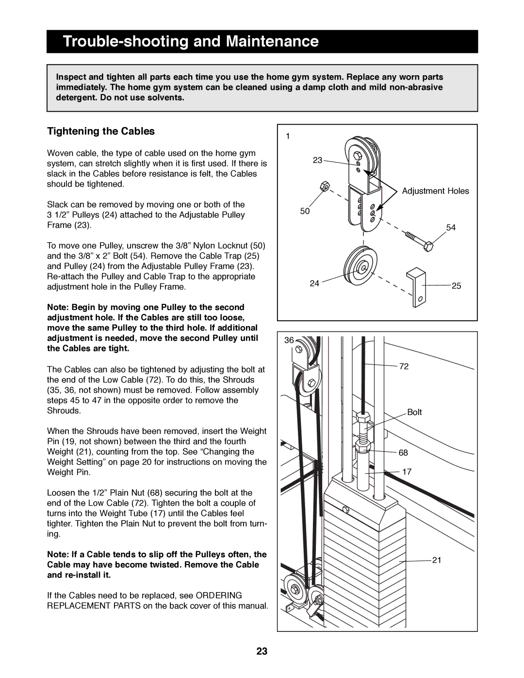
HRSY23080 specifications
The Healthrider HRSY23080 is a versatile and innovative piece of fitness equipment designed for home use, ideal for individuals seeking to enhance their cardiovascular fitness, strength, and overall wellness. This model stands out in the crowded fitness market due to its combination of advanced technologies, user-friendly features, and durable construction.One of the key features of the HRSY23080 is its adjustable resistance levels, allowing users to customize their workouts according to their fitness levels and goals. This adaptability makes it suitable for beginners and seasoned athletes alike, promoting a challenging yet achievable workout experience. The machine also incorporates a comfortable, ergonomic design, which ensures that users can maintain proper form while exercising, reducing the risk of injury.
Equipped with a clear LCD display, the Healthrider HRSY23080 provides real-time feedback on essential workout metrics such as time, distance, speed, and calories burned. This functionality enables users to track their progress and stay motivated throughout their fitness journey. Additionally, the console often features built-in workout programs designed by fitness professionals. These pre-set modes provide variety and organized challenges, which can help prevent workout monotony and enhance user engagement.
The HRSY23080 also emphasizes convenience and usability. Its compact design makes it suitable for small spaces, and many models fold for easy storage. The machine is typically constructed from high-quality materials, ensuring durability and longevity even with regular use. Many users appreciate the quiet operation of the Healthrider, allowing for undisturbed workouts whether at home or in shared living spaces.
Another noteworthy aspect is the incorporation of soft grip handles and padded seating, which contribute to a comfortable workout experience. Some models may also offer additional features such as built-in speakers or Bluetooth connectivity to stream music or exercise programs directly from mobile devices.
In summary, the Healthrider HRSY23080 is designed to cater to diverse fitness needs, combining robust features, adjustable functionalities, and user comfort. It represents a fine choice for those looking to invest in their health and fitness from the comfort of their homes. With its innovative features and ease of use, this machine can help users achieve significant fitness improvements over time.


