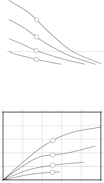
Graco 334014A Performance Charts, Low Pressure Setting Fluid Pressure, Air Consumption

Page 18

Performance Charts

Performance Charts

Low Pressure Setting

Fluid Pressure

Approximate Cycles per Minute

Operating Air Pressure

A

100 psi (0.7 MPa, 7.0 bar)

B

70 psi (0.48 MPa, 4.8 bar)

C

40 psi (0.28 MPa, 2.8 bar)

D

20 psi (0.14 MPa, 1.4 bar)

How to Read the Charts

1.Locate fluid flow rate along bottom of chart.

2.Follow vertical line up to intersection with selected operating air pressure curve.

3.Follow left to scale to read fluid outlet pressure (top chart) or air consumption (bottom chart)

PSI (MPa, bar)

scfm (Nm3/min.)


56

112

168

224

280

100


(0.70, 7.0)


80


(0.55, 5.5)


A


60


(0.41, 4.1)


40


B


(0.28, 2.8)


20


C


(0.14, 1.4)


D


0


0

10

20

30

40

50


(38)

(76)

(114)

(151)

(189)

Fluid Flow — gpm (lpm)

Air Consumption

Approximate Cycles per Minute

56

112

168

224

280

75

(2.1)

60

(1.7)

45


A


(1.3)


30


B


(0.8)


15


C


(0.4)


D


0


0

10

20

30

40

50


(38)

(76)

(114)

(151)

(189)

Fluid Flow — gpm (lpm)

18

334014A

Image 18
Contents Important Safety Instructions Repair/Parts manual. Save these instructionsContents Related ManualsTo Find Your Nearest Distributor To Order Replacement PartsOrdering Information To Specify the Configuration of a New PumpConfiguration Number Matrix Fire and Explosion Hazard Pressurized Equipment HazardPlastic Parts Cleaning Solvent Hazard Equipment Misuse HazardThermal Expansion Hazard Toxic Fluid or Fumes Hazard Burn HazardPersonal Protective Equipment Mounting InstallationTighten Fasteners Before Setup GroundingSee Typical Floor Mount Installation, Air LineAir Exhaust Ventilation KEYFluid Inlet and Outlet Ports Fluid Supply LineFluid Outlet Line 1050HP Aluminum ManifoldsTypical Floor Mount Installation Typical floor mount installationFlush the Pump Before First Use Pressure Relief ProcedureOperation High/Low LeverStart and Adjust the Pump Pump ShutdownLubrication MaintenanceMaintenance Schedule Tighten Threaded ConnectionsTorque Instructions SST Dimensions and MountingAluminum Aluminum and SSTHow to Read the Charts Performance ChartsLow Pressure Setting Fluid Pressure Air ConsumptionHigh Pressure Setting Technical Data Wetted parts Fluid Temperature RangeFluid Temperature Range Non-wetted external partsGraco Standard Husky Pump Warranty Graco Information