Baldor BSC 7107 DC manual AC Power Connection Refer to Figure, Speed Potentiometer Refer to Figure

Page 9

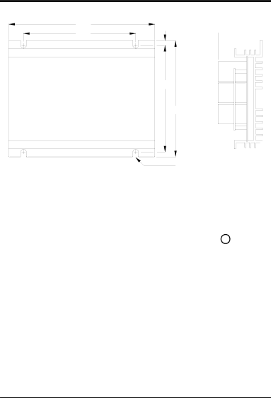
Figure 2-1 Mounting Diagram

9.00

7.50

Top View

0.20

2.90

6.30

6.70

7/32 dia. (4 places) End View

AC Power Connection Refer to Figure 2-2.

A fused 120 VAC power source is required. A 12 AMP fuse should be used.

1.Be sure the AC source is disconnected (OFF).

2.Be sure the appropriate fuse is installed at the source.

3.Connect the AC power to P1 pins AC and AC.

4.Connect plant earth ground to the chassis connection +

Speed Potentiometer Refer to Figure 2-2.

1.Rotate the pot fully CCW (Counter clockwise). Measure the resistance between the wiper and each terminal.

2.Connect the terminal with the most resistance (5KW) to Rmax (P4 pin HI).

3.Connect the terminal with the least resistance (0KW) to Rmin (P4 pin LO).

4.Connect the wiper to Wiper (P4 pin W).

2-2 Receiving & Installation

Image 9
Contents MN1231 BSC DC Brushless Control Installation and Operating ManualTable of Contents Ii Table of Contents Introduction Section General InformationLimited Warranty Precautions Safety NoticeBe sure the system is properly grounded before Installation Section Receiving & InstallationControl Installation ReceivingSpeed Potentiometer Refer to Figure AC Power Connection Refer to FigureControl Connection Locations Connect the three motor leads to P1 terminals as follows Sensor and Motor Connections Refer to FigureReverse Operation 1st Time Power Up Procedure or after a motor is replaced Current Limit Adjustment Section AdjustmentsAdjusting Closed Loop Gain Minimum Speed AdjustmentSection Specifications and Data SpecificationsDimensions Hall Signal Timing Diagram Box Fort Smith, AR 479 Fax 479