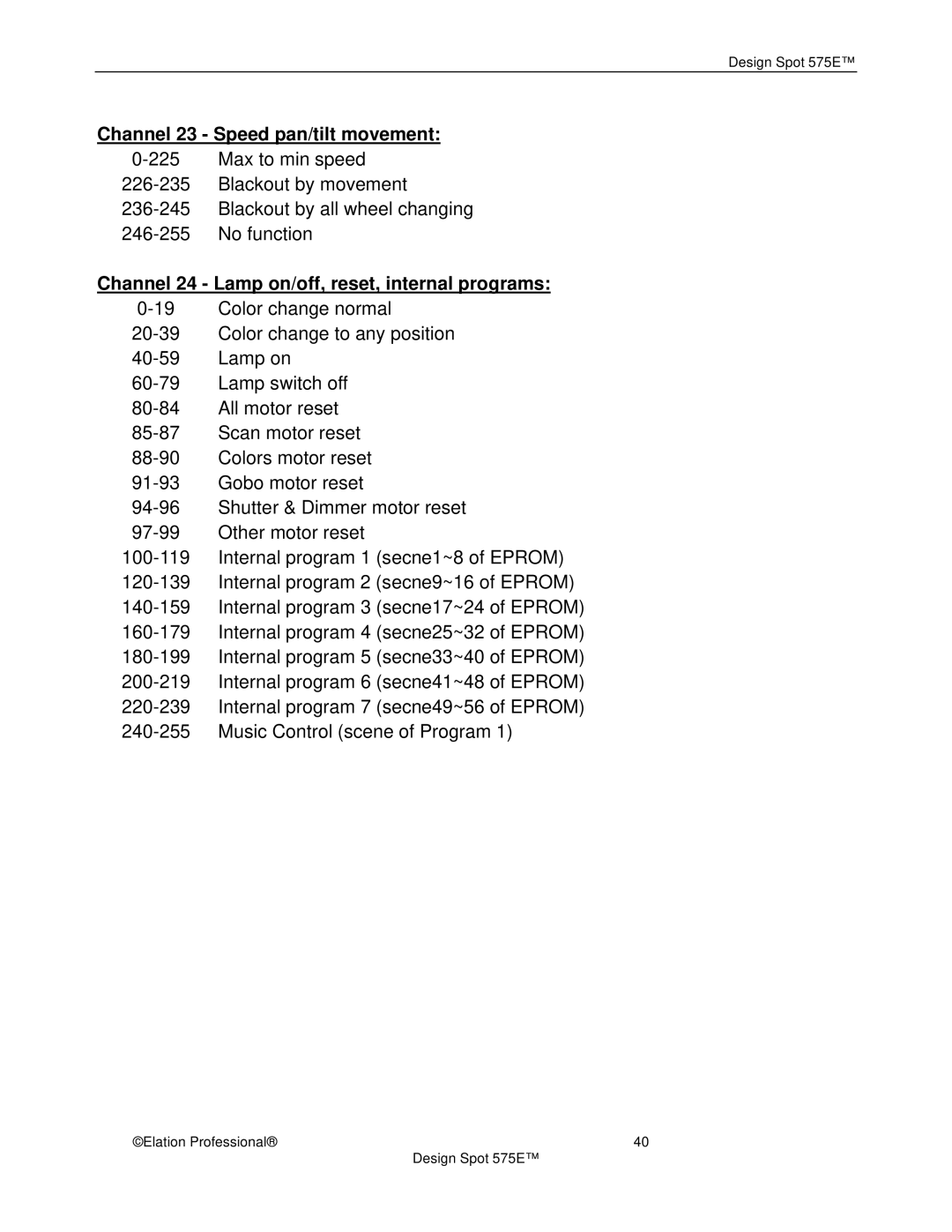
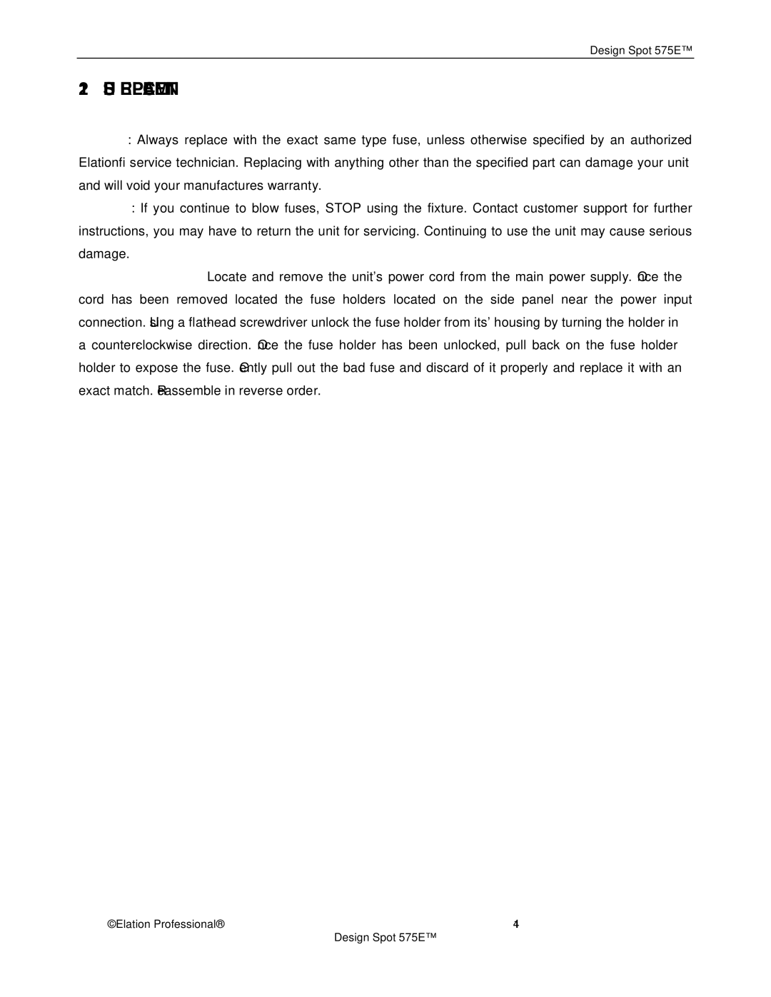
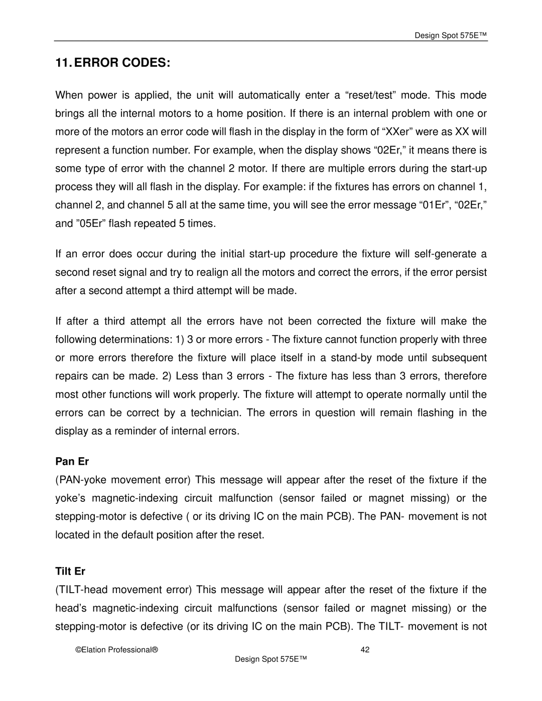
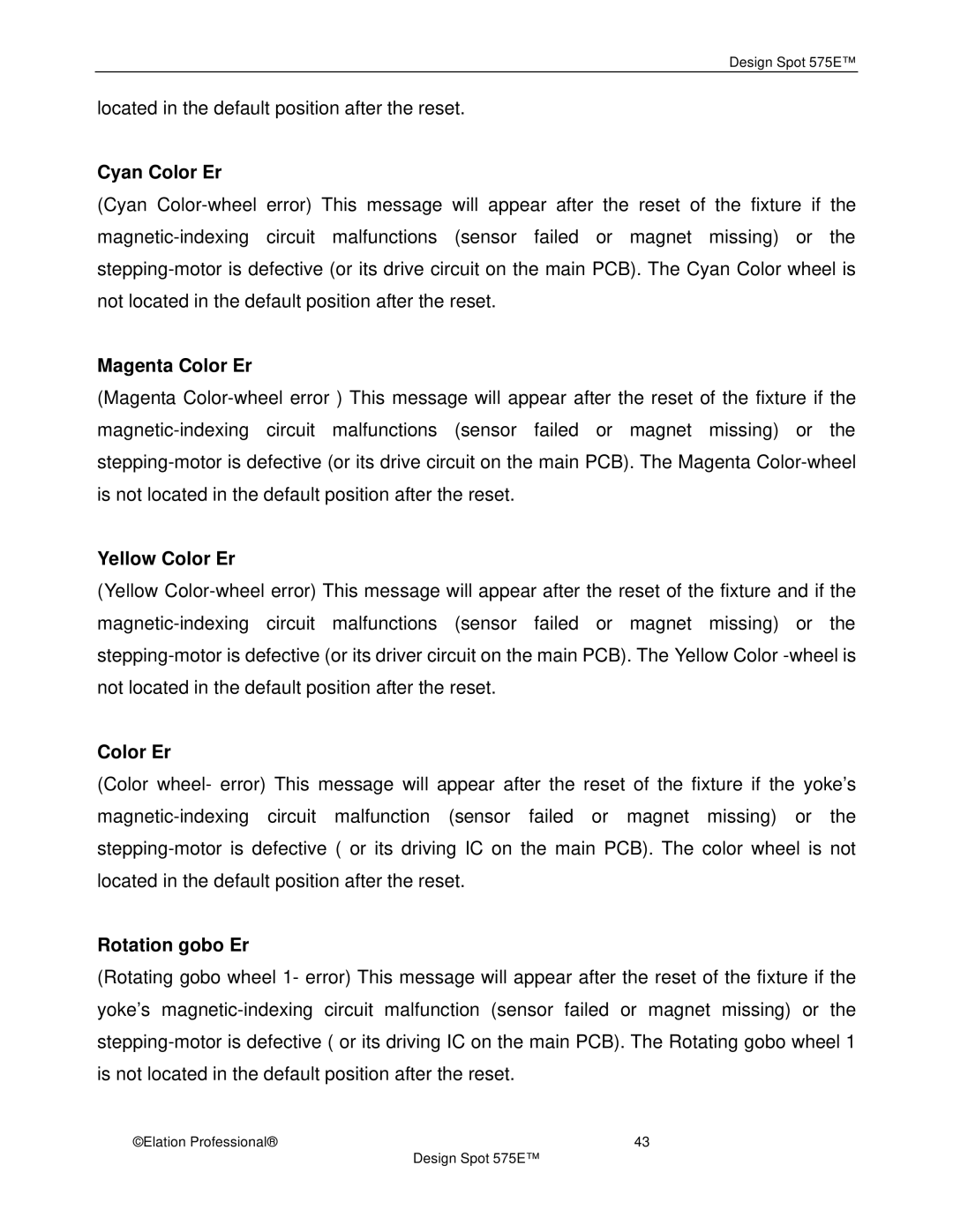
Elation Professional 575E manual DMX address setting, Display the DMX 512 value of each channel

Page 24


Design Spot 575E™


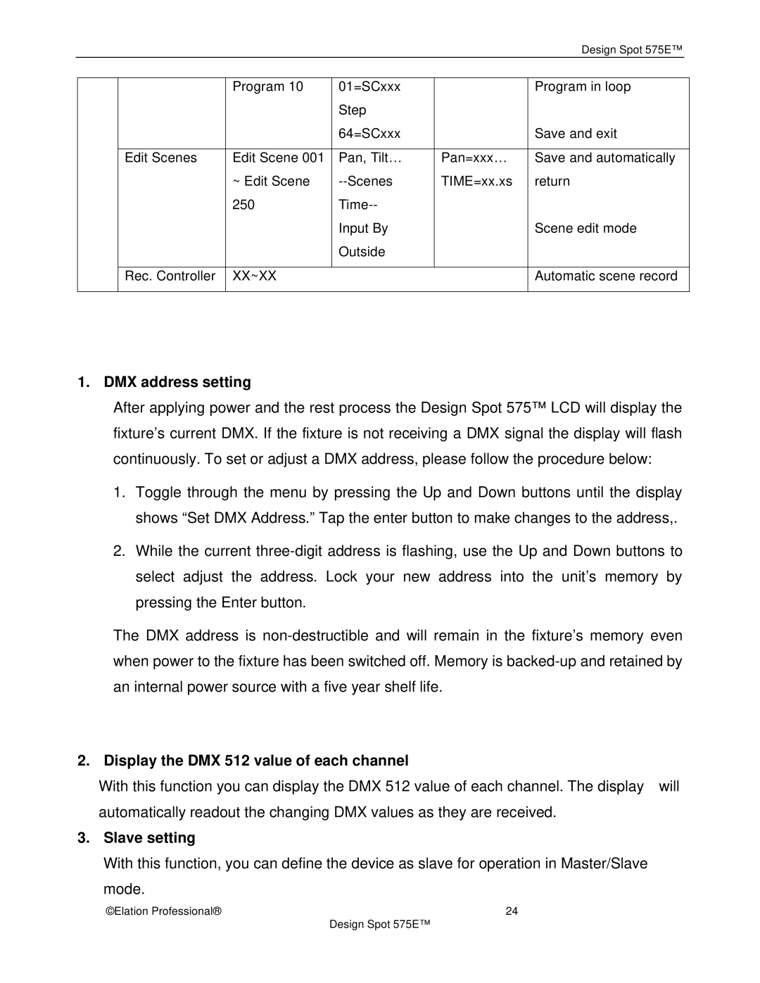
Program 10

01=SCxxx


Program in loop


Step


64=SCxxx


Save and exit


Edit Scenes

Edit Scene 001

Pan, Tilt…

Pan=xxx…

Save and automatically


~ Edit Scene

--Scenes

TIME=xx.xs

return


250

Time--


Input By


Scene edit mode


Outside


Rec. Controller

XX~XX


Automatic scene record


1. DMX address setting

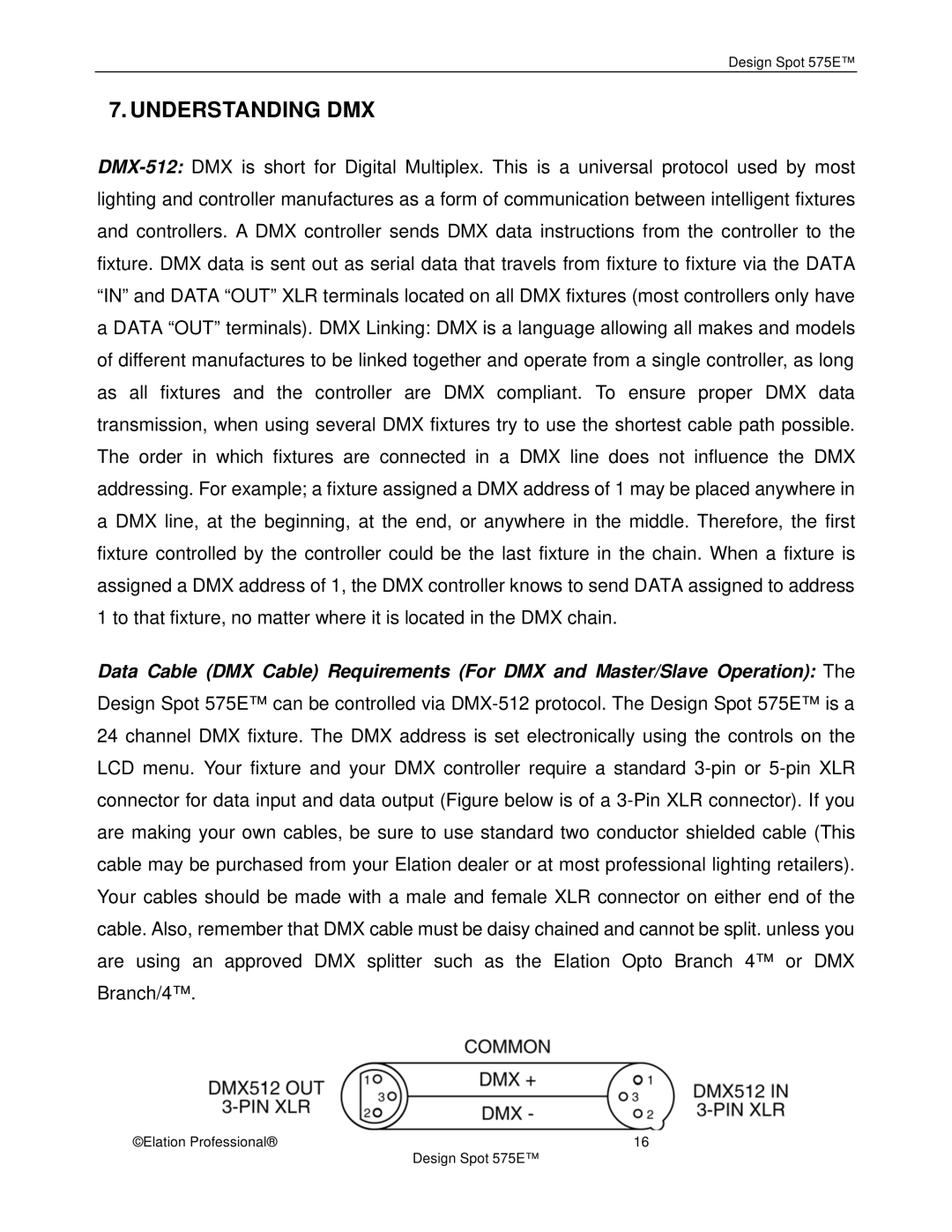
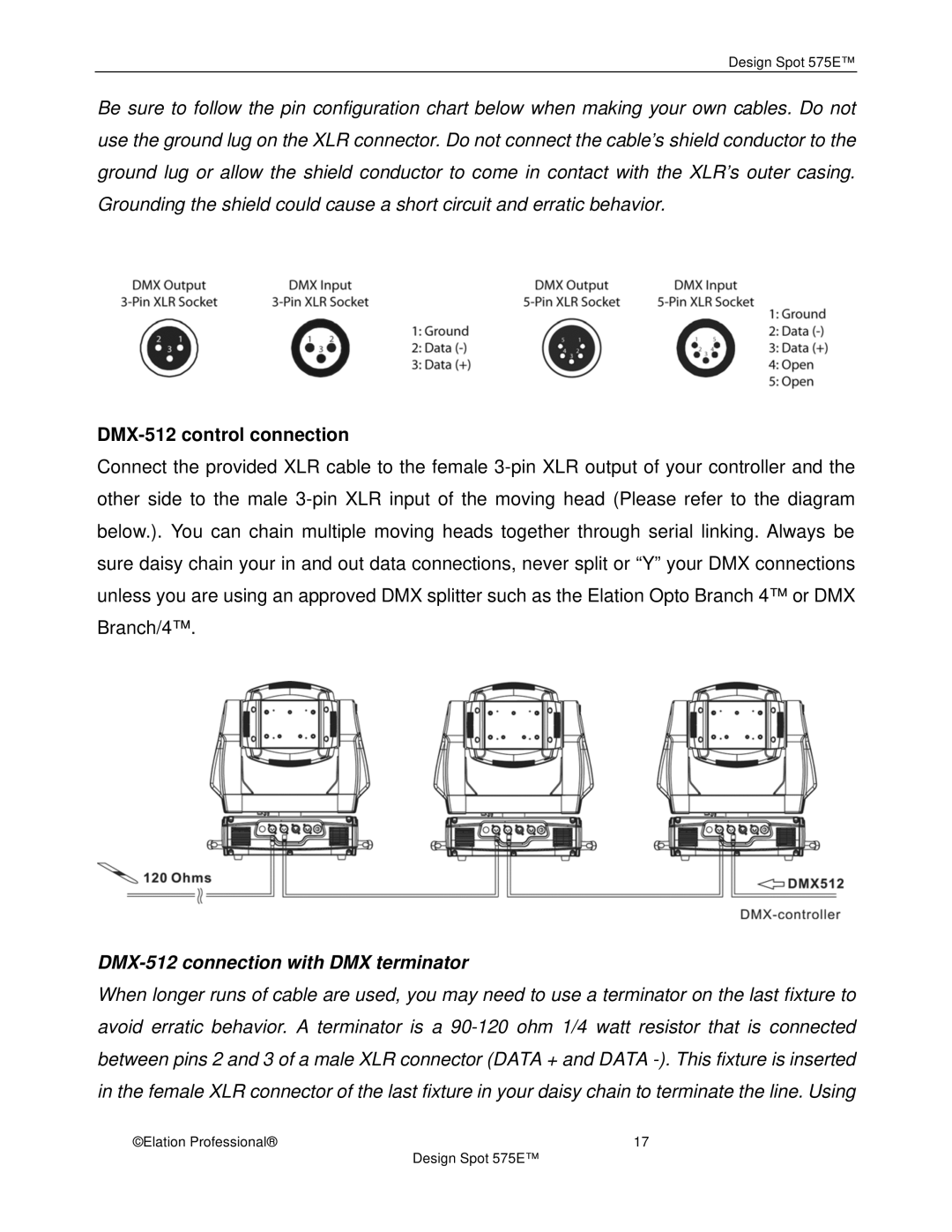
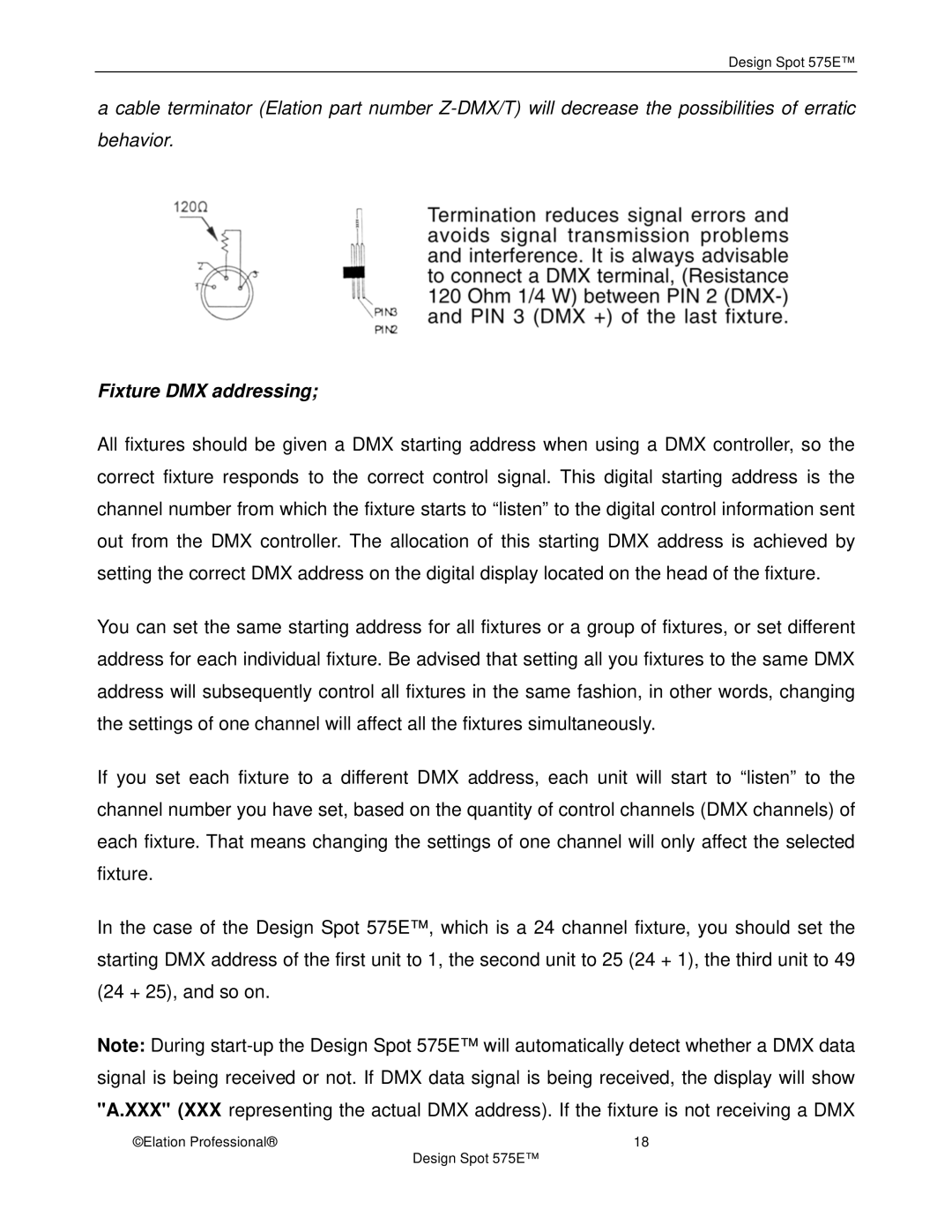
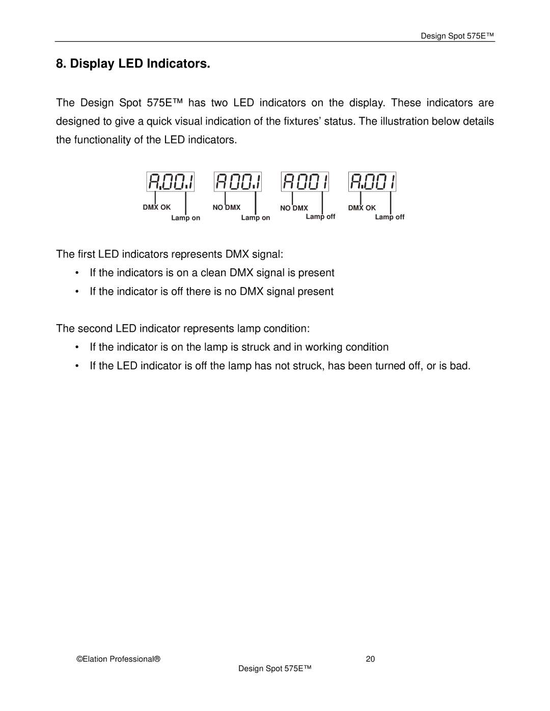
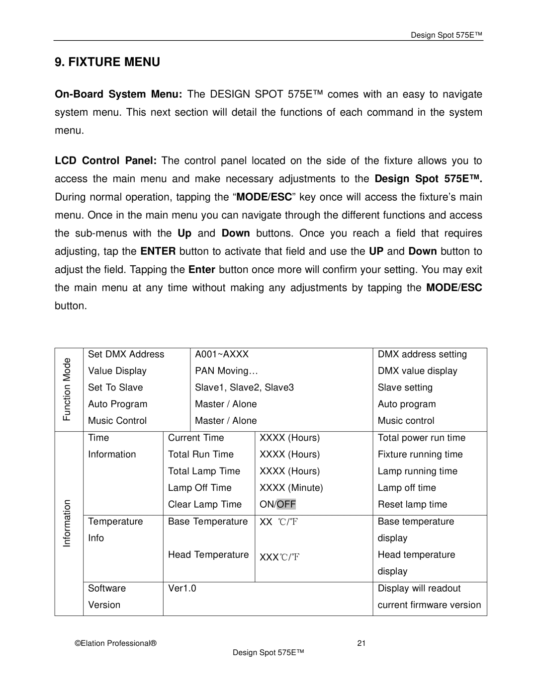
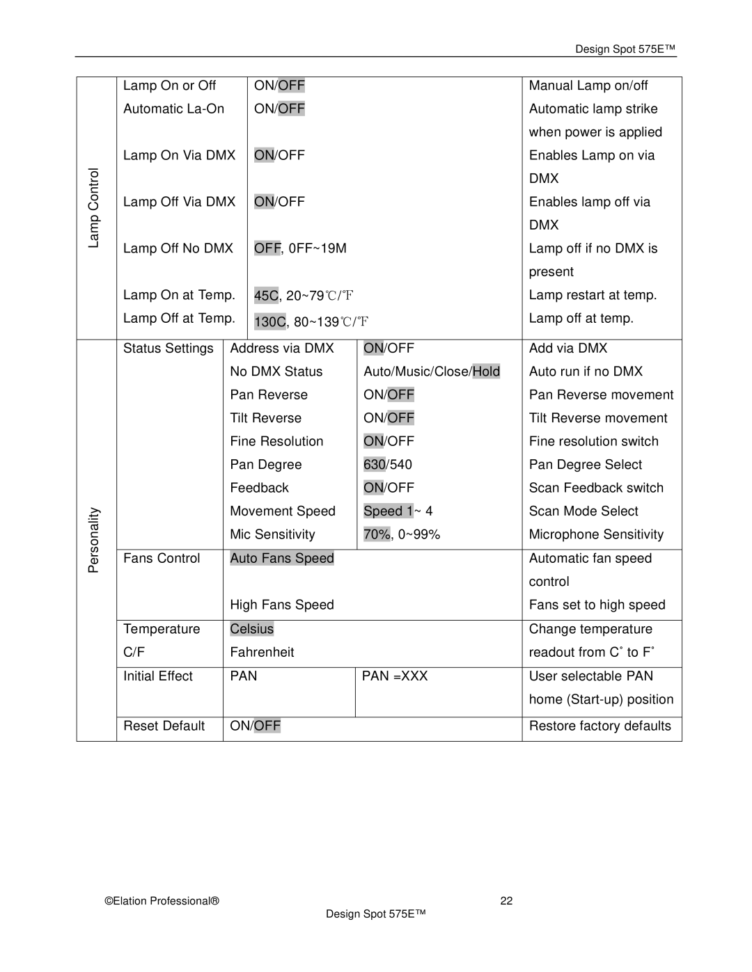
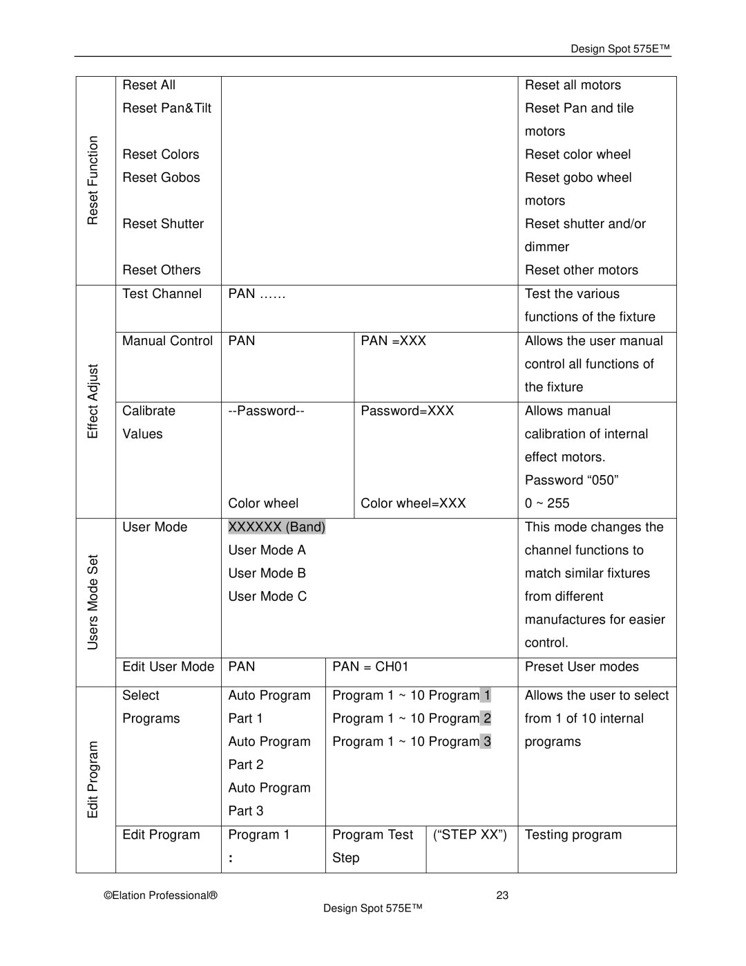
After applying power and the rest process the Design Spot 575™ LCD will display the fixture’s current DMX. If the fixture is not receiving a DMX signal the display will flash continuously. To set or adjust a DMX address, please follow the procedure below:

1.Toggle through the menu by pressing the Up and Down buttons until the display shows “Set DMX Address.” Tap the enter button to make changes to the address,.

2.While the current three-digit address is flashing, use the Up and Down buttons to select adjust the address. Lock your new address into the unit’s memory by pressing the Enter button.

The DMX address is non-destructible and will remain in the fixture’s memory even when power to the fixture has been switched off. Memory is backed-up and retained by an internal power source with a five year shelf life.

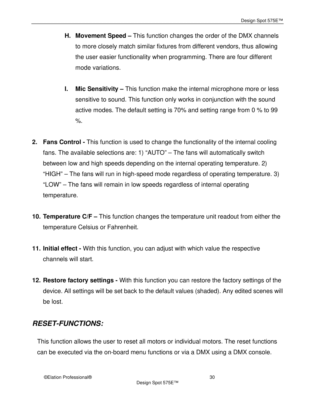
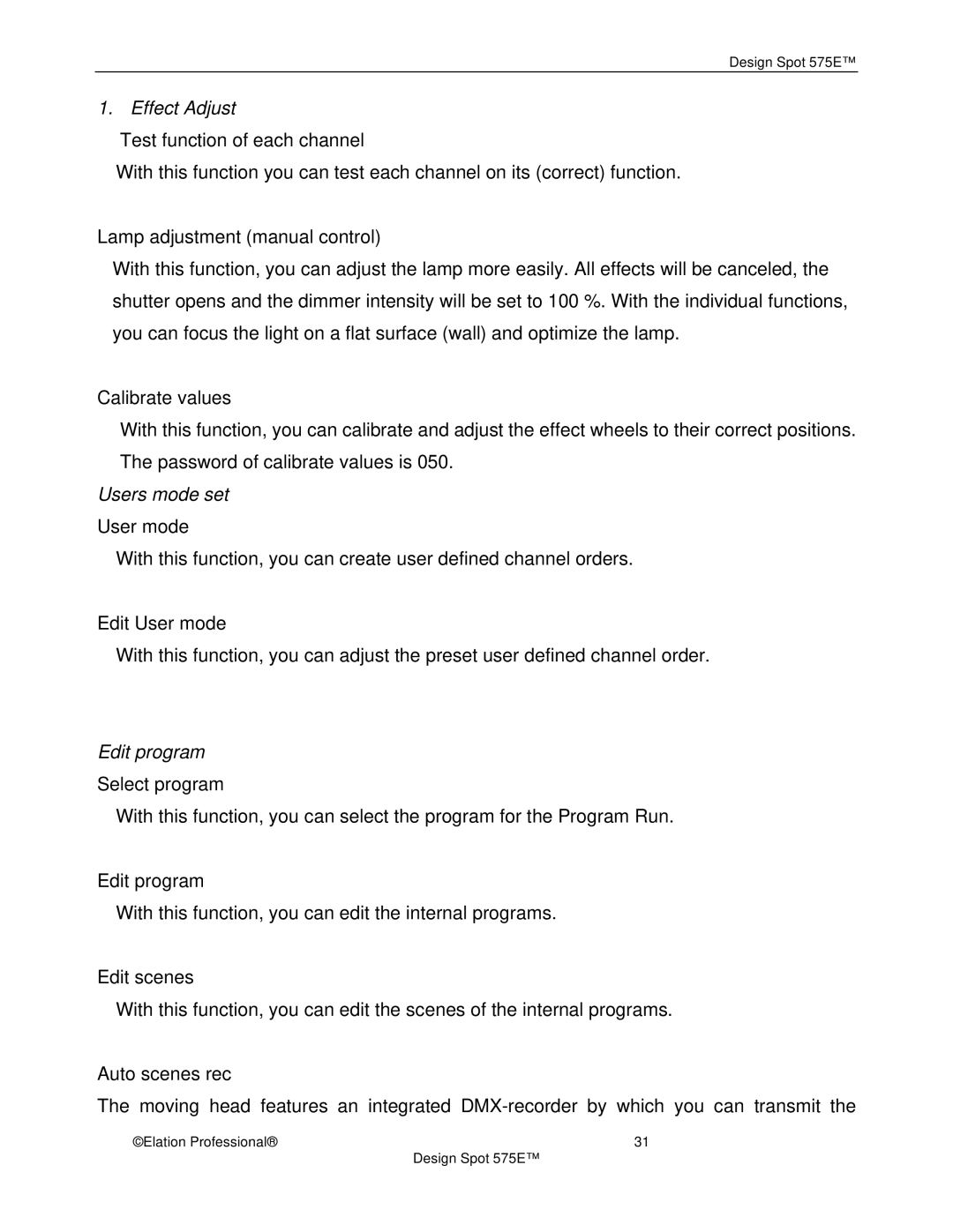
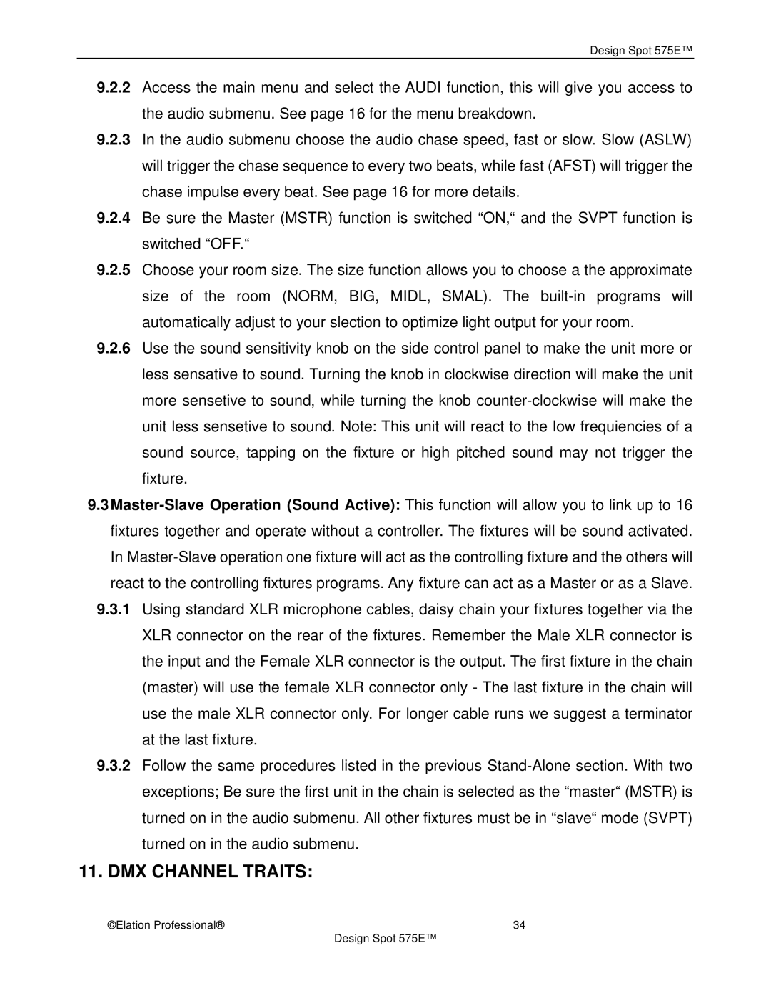
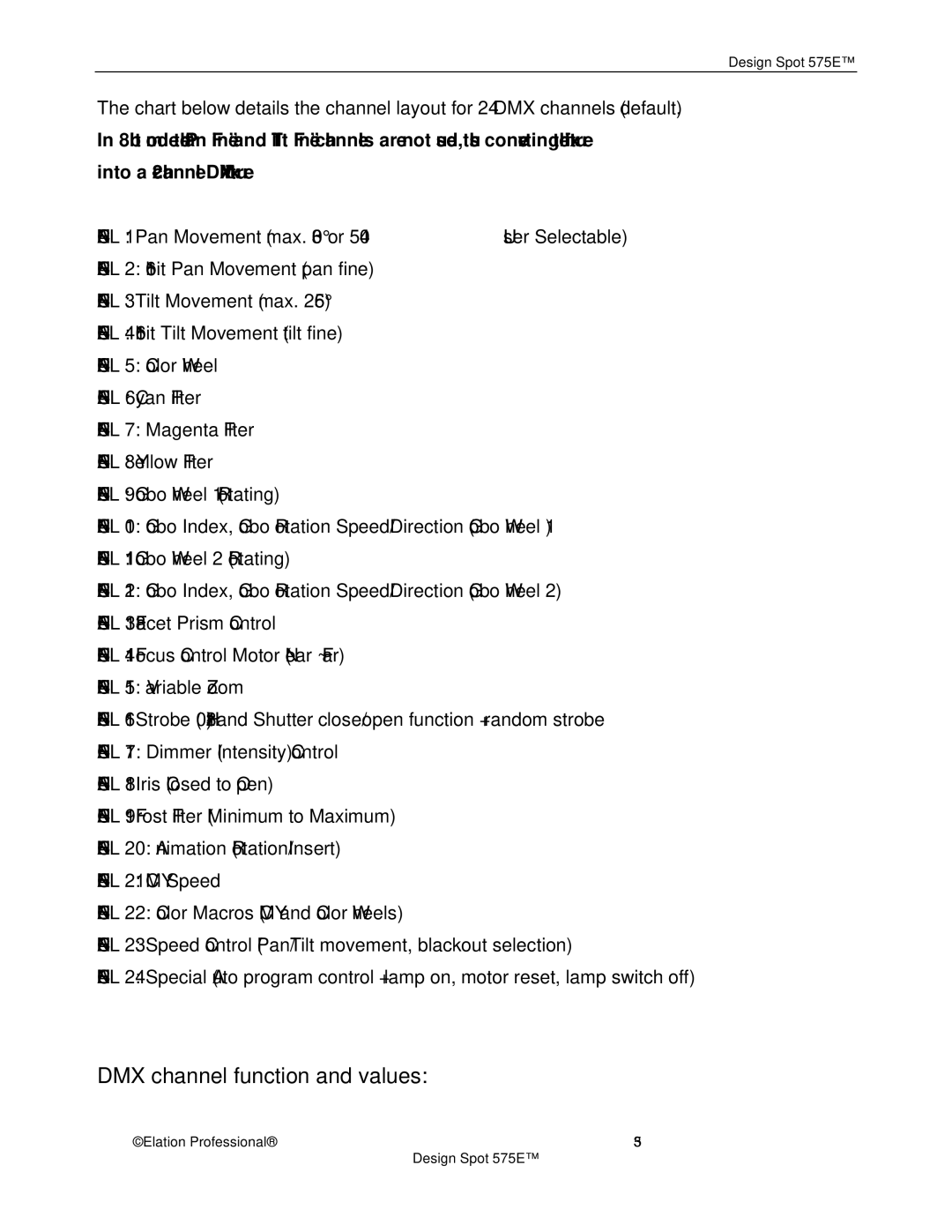
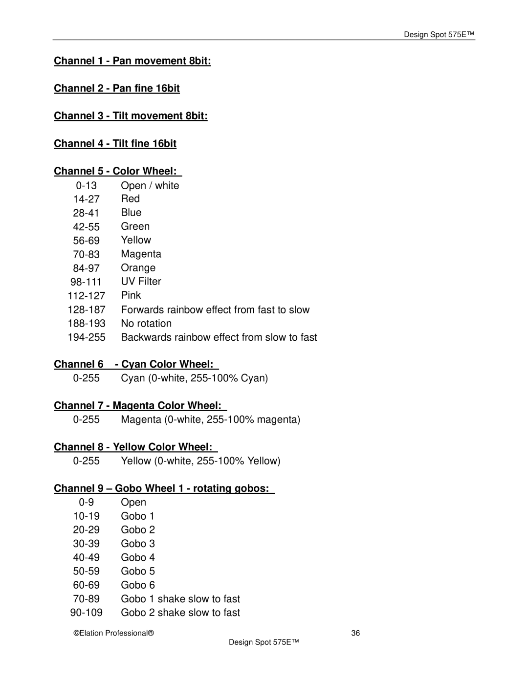
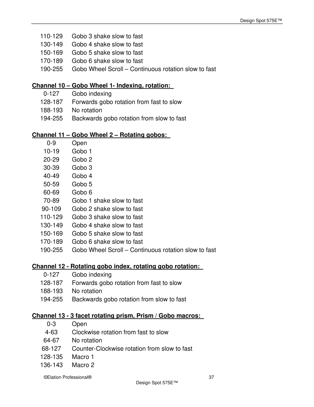
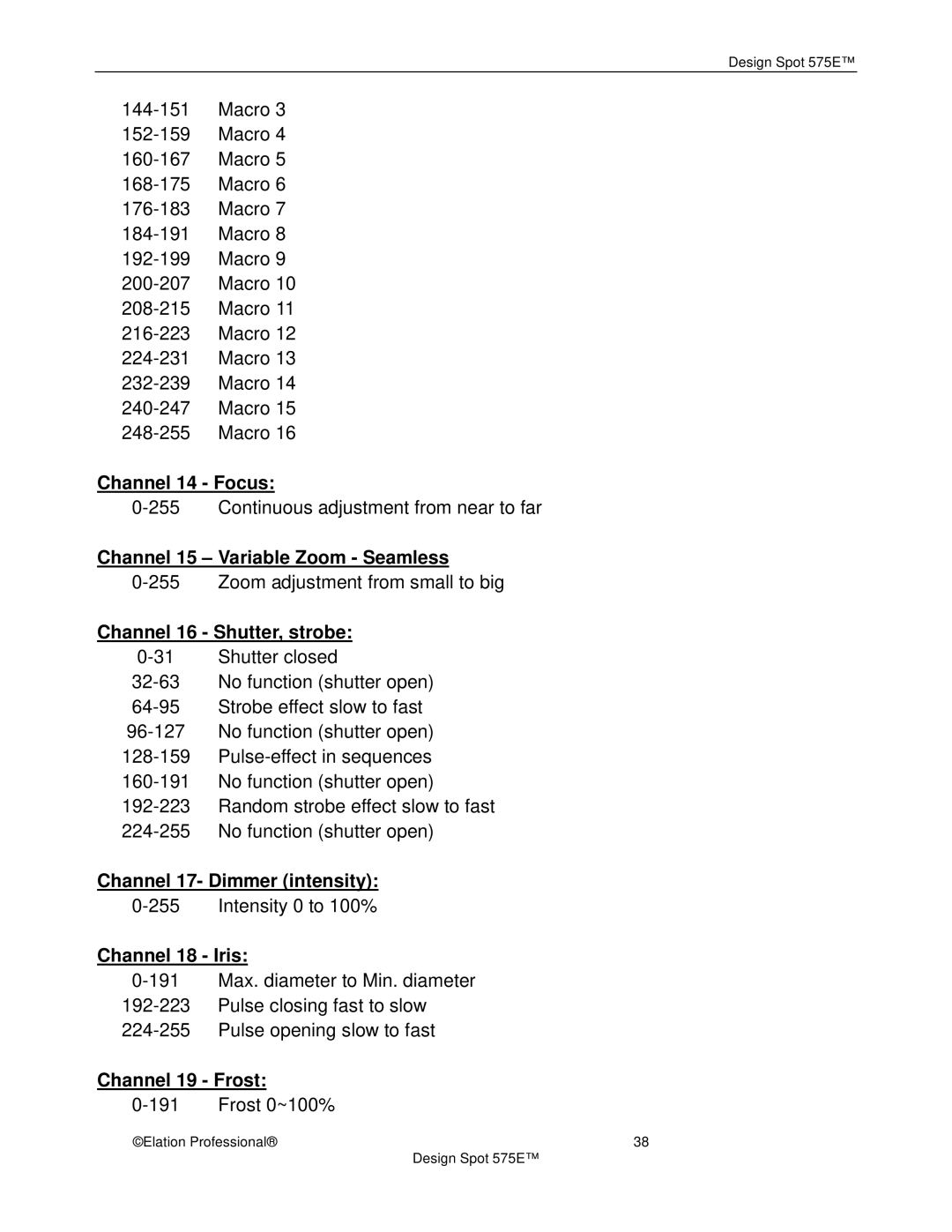
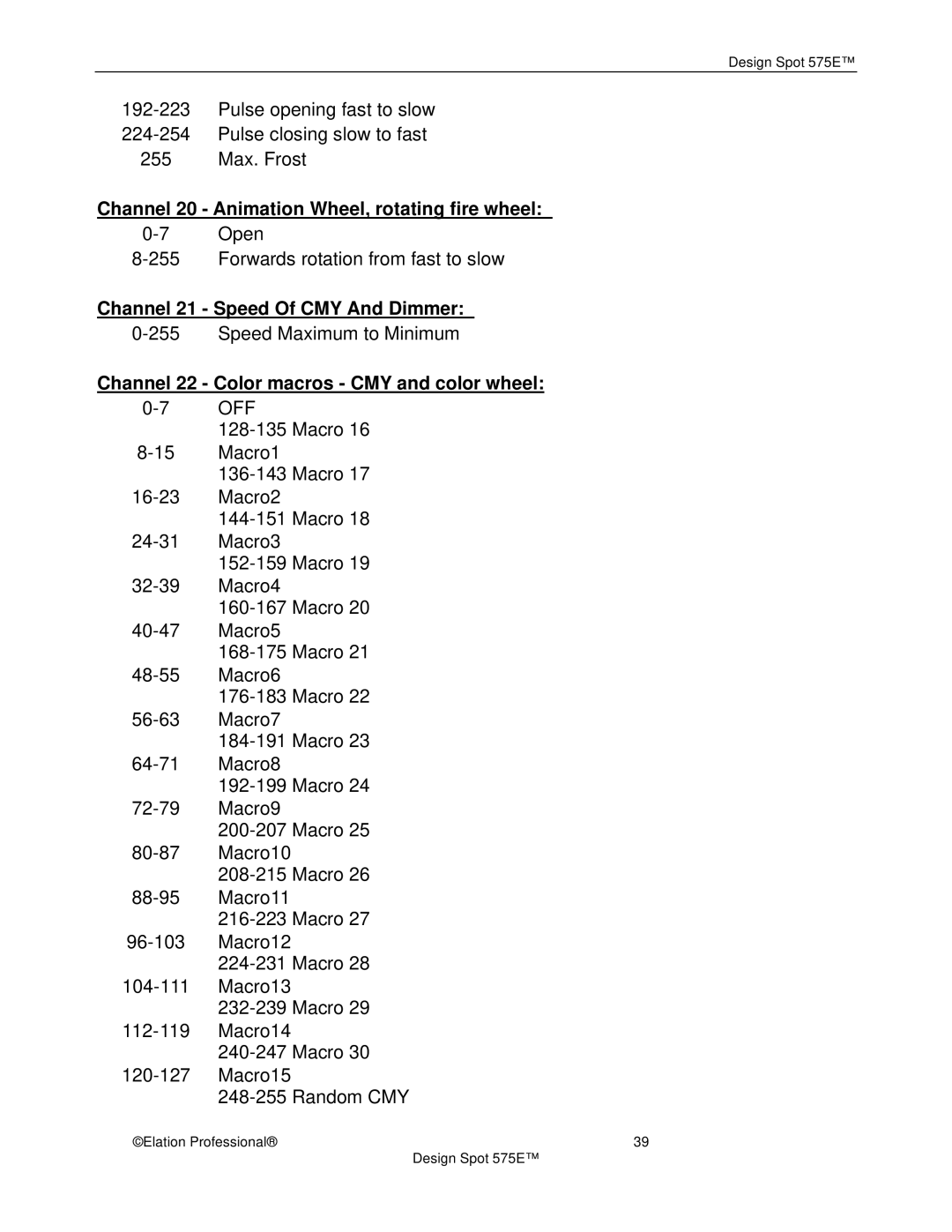
2. Display the DMX 512 value of each channel

With this function you can display the DMX 512 value of each channel. The display will automatically readout the changing DMX values as they are received.

3.Slave setting

With this function, you can define the device as slave for operation in Master/Slave

mode.

©Elation Professional®

24


Design Spot 575E™

Image 24
Contents Design Spot 575E Contents General Information Design Spot 575E Never open this fixture while in use Safety Instructions Design Spot 575E Features General Guidelines Lamp Installation Instructions Safety RegulationsInstallation Procedure OK  No  Lamp OptimizationDesign Spot 575E Mounting and Installation MountingMounting points Clamp MountingSecuring the Design Spot 575E Understanding DMX DMX-512 control connection DMX-512 connection with DMX terminatorFixture DMX addressing Design Spot 575E Display LED Indicators Fixture Menu A001~AXXXDMX PAN DMX address setting Slave settingDisplay the DMX 512 value of each channel Auto Program Music controlTime information Current time Machine on timeClear lamp time Temp. InfoSoftware version Lamp on/offAutomatic La-On Lamp on via external controllerLamp off via external controller Lamp Off if no DMXStatus setting Fixture SettingsController Settings Channel 3 to 164 256+164=420 RESET-FUNCTIONS Effect Adjust Design Spot 575E Operation DMX Channel Traits DMX channel function and values Channel 6 Cyan Color Wheel Channel 7 Magenta Color WheelChannel 8 Yellow Color Wheel Channel 9 Gobo Wheel 1 rotating gobosChannel 10 Gobo Wheel 1- Indexing, rotation Channel 11 Gobo Wheel 2 Rotating gobosChannel 12 Rotating gobo index, rotating gobo rotation Channel 13 3 facet rotating prism, Prism / Gobo macrosChannel 14 Focus Channel 16 Shutter, strobeChannel 17- Dimmer intensity Channel 18 IrisChannel 20 Animation Wheel, rotating fire wheel Channel 21 Speed Of CMY And DimmerChannel 22 Color macros CMY and color wheel Channel 24 Lamp on/off, reset, internal programs Channel 23 Speed pan/tilt movementFuse Replacement Error Codes Pan ErTilt Er Cyan Color Er Magenta Color ErYellow Color Er Color ErGobo Rotation Er Prism Rotation ErShutter, Strobe Er Focus ErZoom Er Iris ErFire Wheel Er Cleaning and Maintenance Disconnect from mains before starting maintenance operationYear Limited Warranty Design Spot 575E Photometric Data Gobos Dimensional Drawings Circuit Schematic Technical Specifications Optical systemElation Professional