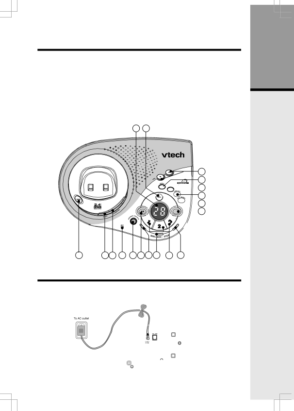
Base Unit Layout
1. | In Use LED | 10. | Delete |
2. | Charging LED | 11. | Repeat/Slow |
3. | Message Window Display | 12. | Skip/Quick |
4. | Page key | 13. | Mailbox/Stop keys |
5. | Volume keys | 14. | Answer On/Off key |
6. | Menu | 15. | Microphone |
7. | Change | 16. | Mailbox/Stop LED 1 |
8. | Time/Set | 17. | Mailbox/Stop LED 2 |
9. | Record/Memo | 18. | Mailbox/Stop LED 3 |
| 3 | 10 |
|
5
6
![]()
![]()
![]() 7
7
8
![]() 9
9 ![]()
![]() 12
12
4 | 1 | 2 | 15 | 14 | 11 16 | 17 | 13 | 18 |
Setup
Connecting Power to Base Unit/Handset Charger
1.Plug the AC power adapter into an electrical outlet, and the DC connector into the bottom of the Base Unit.
Getting Started
5