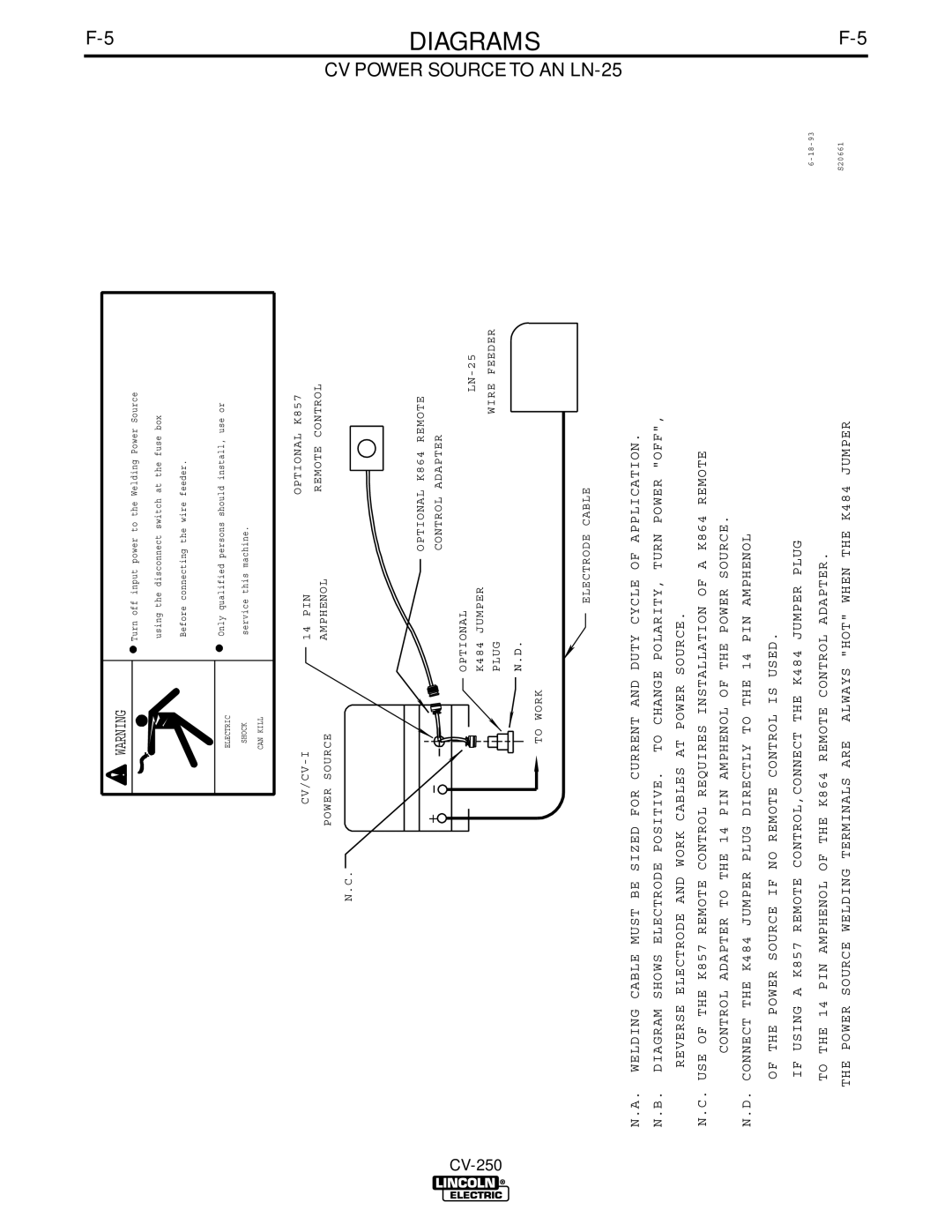
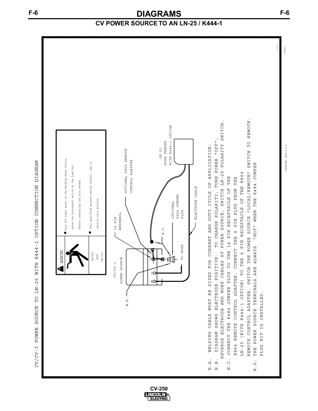
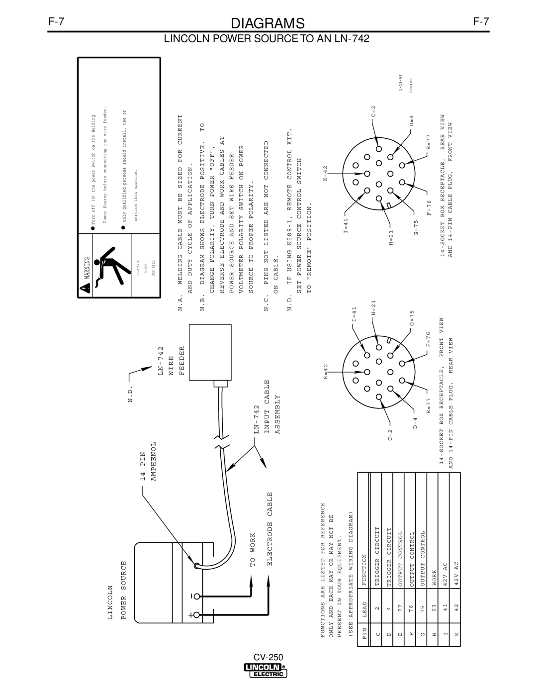
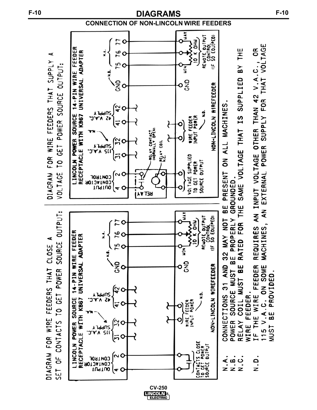
Lincoln Electric CV-250 manual TWIST-MATE Cable Plug Installation Instructions

Page 36

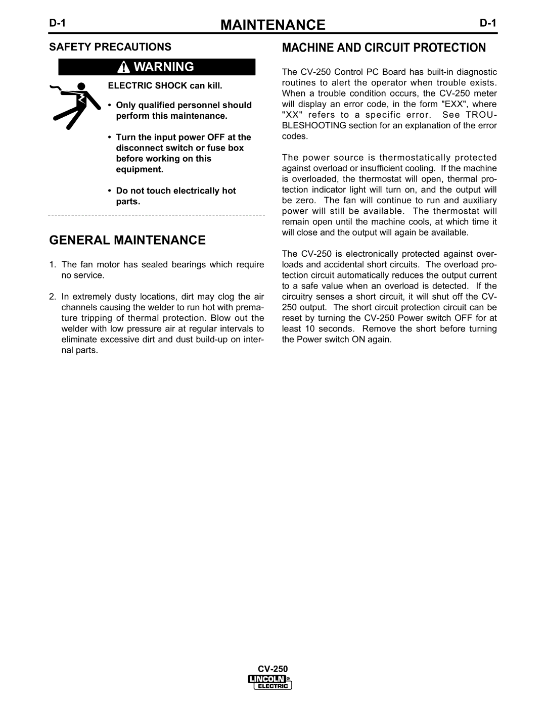
F-9

DIAGRAMS

F-9


TWIST-MATE CABLE PLUG INSTALLATION INSTRUCTIONS


TWIST-MATE WELDING CABLE PLUG INSTALLATION INSTRUCTIONS

TURN THE POWER SWITCH OF THE WELDING POWER

SOURCE "OFF" BEFORE INSTALLING PLUGS ON CABLES

OR WHEN CONNECTING OR DISCONNECTING PLUGS TO

WELDING POWER SOURCE.

1.CHECK THAT THE CONNECTOR BOOT IS MARKED FOR THE APPROPRIATE CABLE SIZE PER TABLE BELOW; AND SKIN CABLE JACKET TO LENGTH SPECIFIED:

BOOT MARKING

AMERICAN (EUROPEAN)

RANGE


CABLE SKIN LENGTH


CABLE SIZE


2


mm


1

INCH

(25.4mm)


35-50

#2-#1

(35-50


)


50-70

1/0-2/0

(50

-70

mm

2

1

INCH

(25.4mm)

)

70-95

2/0-3/0


2

1.5 INCH (38.1mm)

(70

-95

mm

)

2.If necessary, trim cable end of boot at groove(s) to match cable diameter. Boot must fit tightly enough to seal around outside diameter of cable. NOTE: Some boots are designed to accommodate different cable diameters without trimming. These boots do not have grooves at the cable end. Soap or other non petroleum based lubricant will help to slide the boot over the cable.

3. Slide rubber boot onto cable end.


BOOT


WELDING CABLE


SEE

ABOVE

TRIM

4.Slide the copper tube into the brass plug.

5. Insert cable into copper tube.

COPPER TUBE

6.Tighten set screw(s) to collapse copper tube. Screw(s)

must apply firm pressure against welding cable. The top of the set screw(s) will be nearly flush or below the surface of the brass plug after tightening.

7.Slide rubber boot over brass plug. The rubber boot must be positioned to completely cover all electrical surfaces after the plug is locked into the receptacle.

SET SCREW

(70-95 size may have 2 set screws)

BRASS PLUG

9-20-91J

S18737

CV-250

Image 36
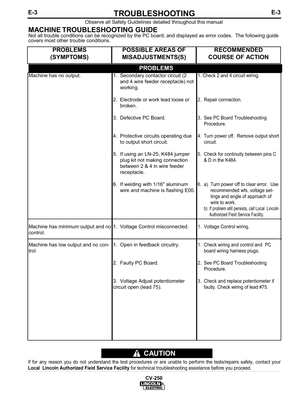
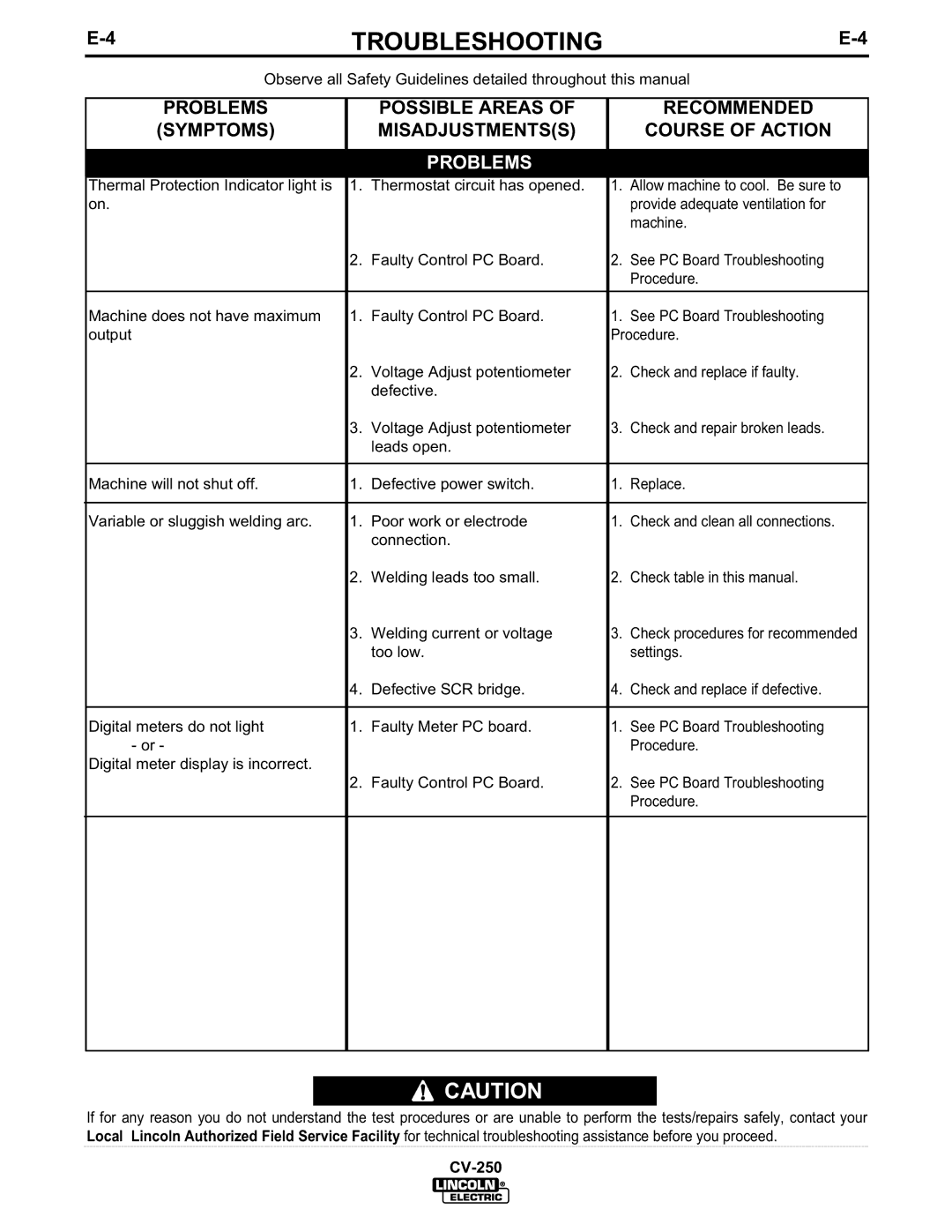
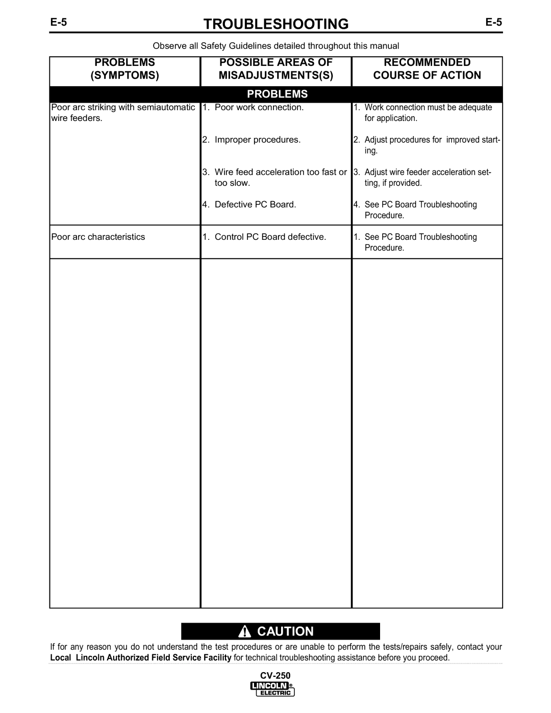
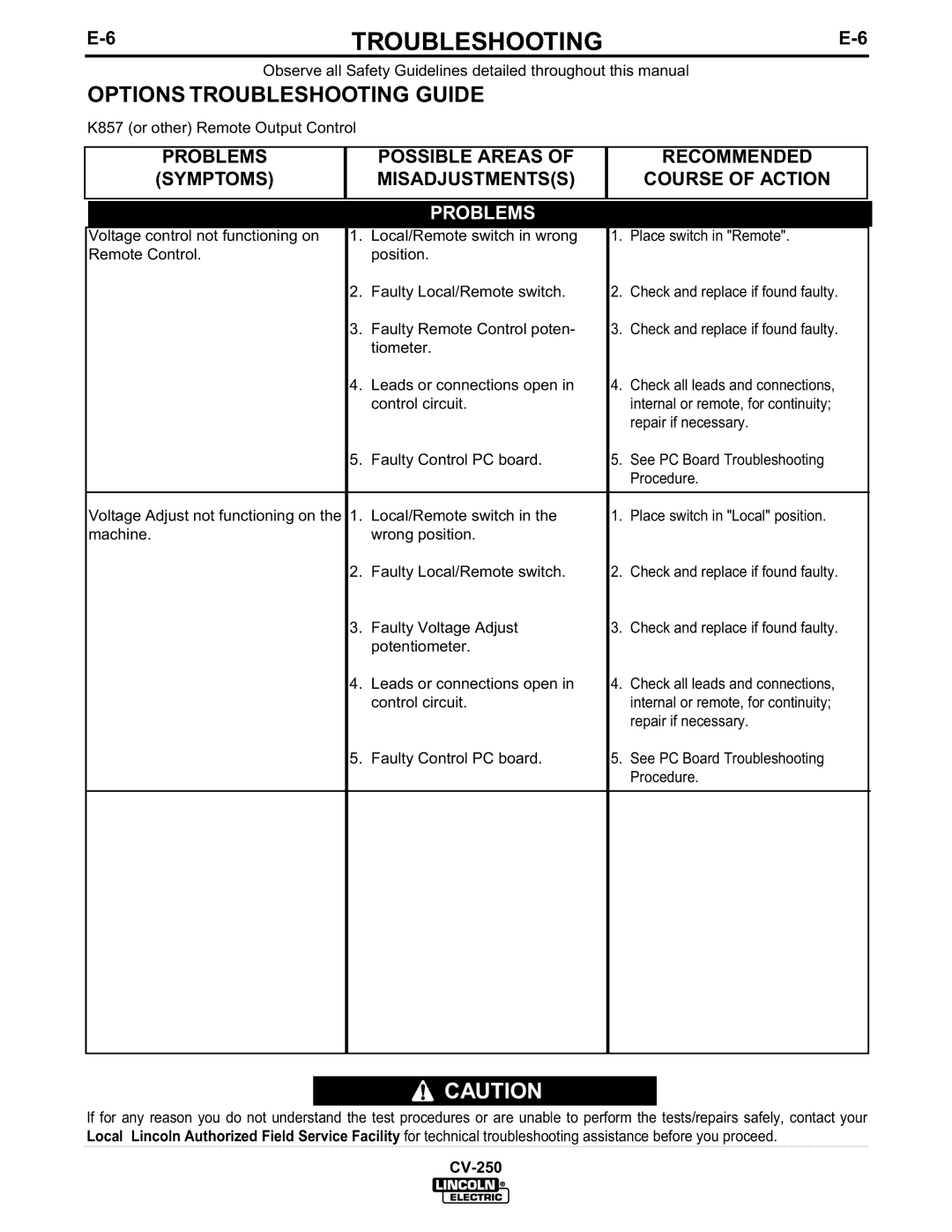
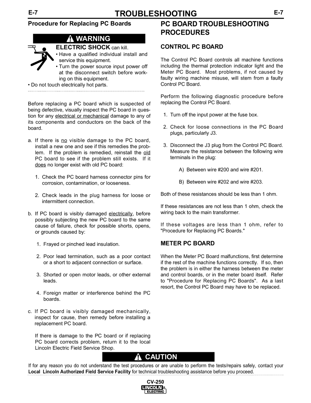
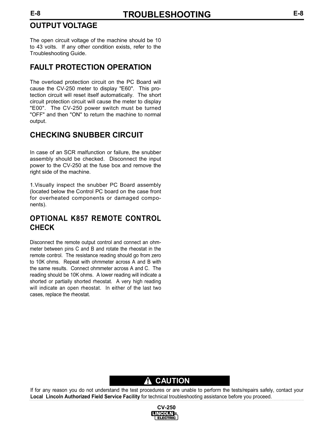
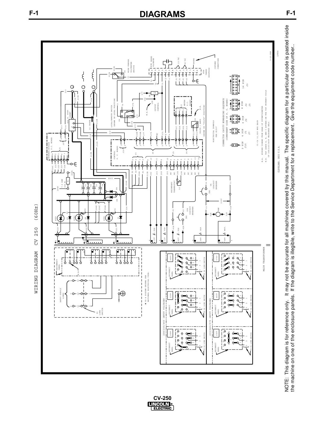
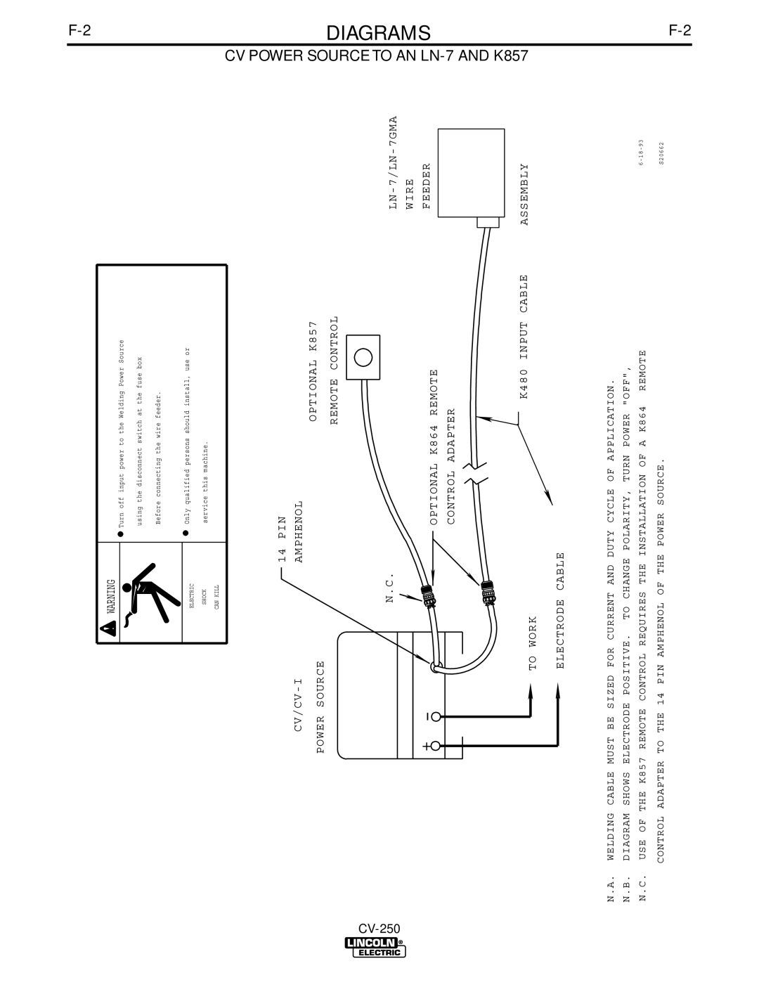
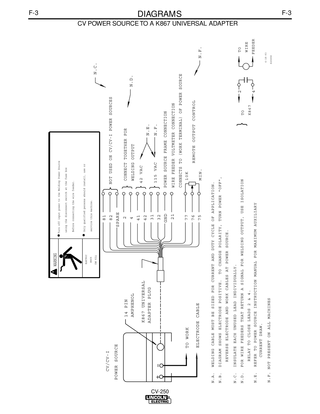
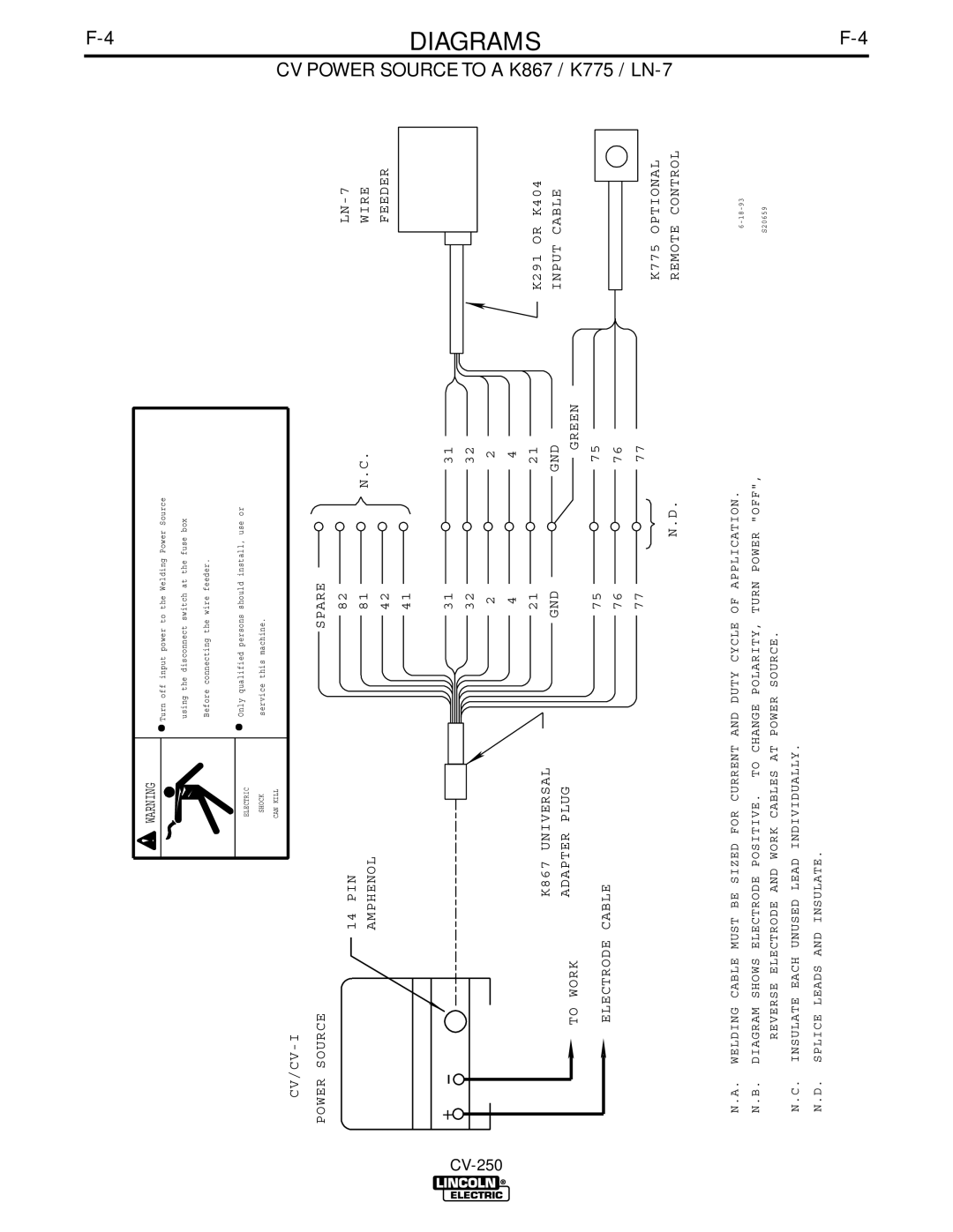
Contents Safety Depends on You IdealarcSafety California Proposition 65 WarningsElectric Shock can kill Welding Sparks can cause fire or explosion IiiPrécautions DE Sûreté Sûreté Pour Soudage a L’ArcThank You Table of Contents Installation Technical Specifications Idealarc CV-250Safety Precautions Select Suitable LocationInput Connections StackingField Installed Options Output ConnectionsParalleling Operation Operating InstructionsGeneral Warnings Operational Features and Controls Design FeaturesPower Source Operation General DescriptionControls and Settings Thermal Protection Indication LightIndicates Warning Information Located on Right Case Side Voltage ControlC. Output Connectors Output Panel ConnectionsAuxiliary Power Starting the MachineOverload Protection Accessories Factory Installed OPTIONS/ACCESSORIESCompatible Lincoln Equipment Maintenance General MaintenanceSafety Precautions Machine and Circuit Protection1TROUBLESHOOTINGE-1 HOW to USE Troubleshooting GuideTroubleshooting BUILT-IN Diagnostic Routines and Error CodesError Code Trouble Remedy Machine Troubleshooting Guide ProblemsPossible Areas Recommended Symptoms Poor arc striking with semiautomatic Poor work connection Options Troubleshooting Guide Control PC Board Meter PC BoardFault Protection Operation Optional K857 Remote Control CheckOutput Voltage Checking Snubber CircuitWiring Diagram CV 250 60Hz Diagrams CV Power Source to AN LN-7 and K857Source to a K867 AdapterPower Source to a K867 / K775 / LN CV Power Source to AN LN-25 250CV Power Source to AN LN-25 / K444-1 Lincoln Power Source PIN Amphenol Installation Instructions TWIST-MATE Cable Plug Installation Instructions Connection of NON-LINCOLN Wire Feeders Dimension Print How To Read Shop Drawings $700.00Precaucion Warnung