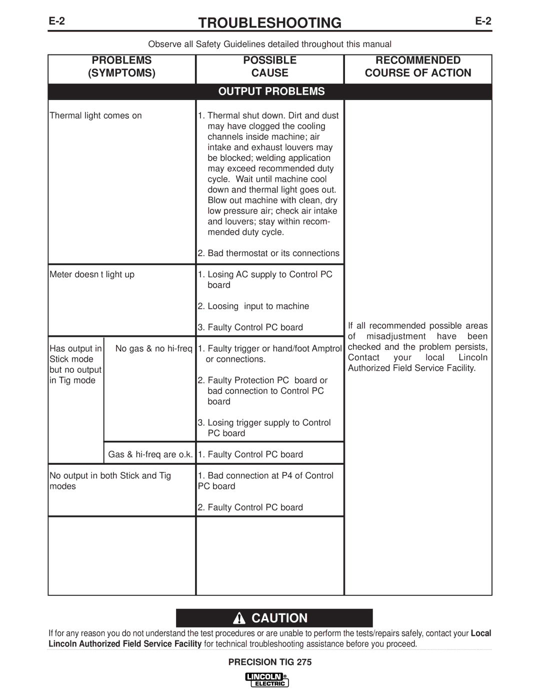
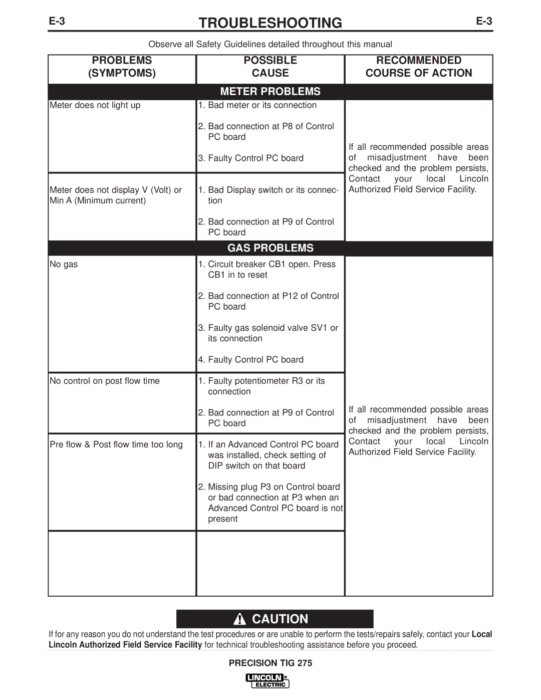
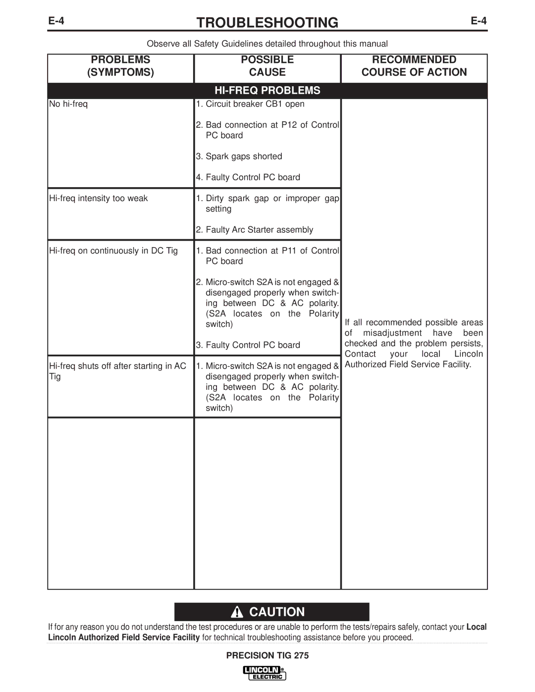
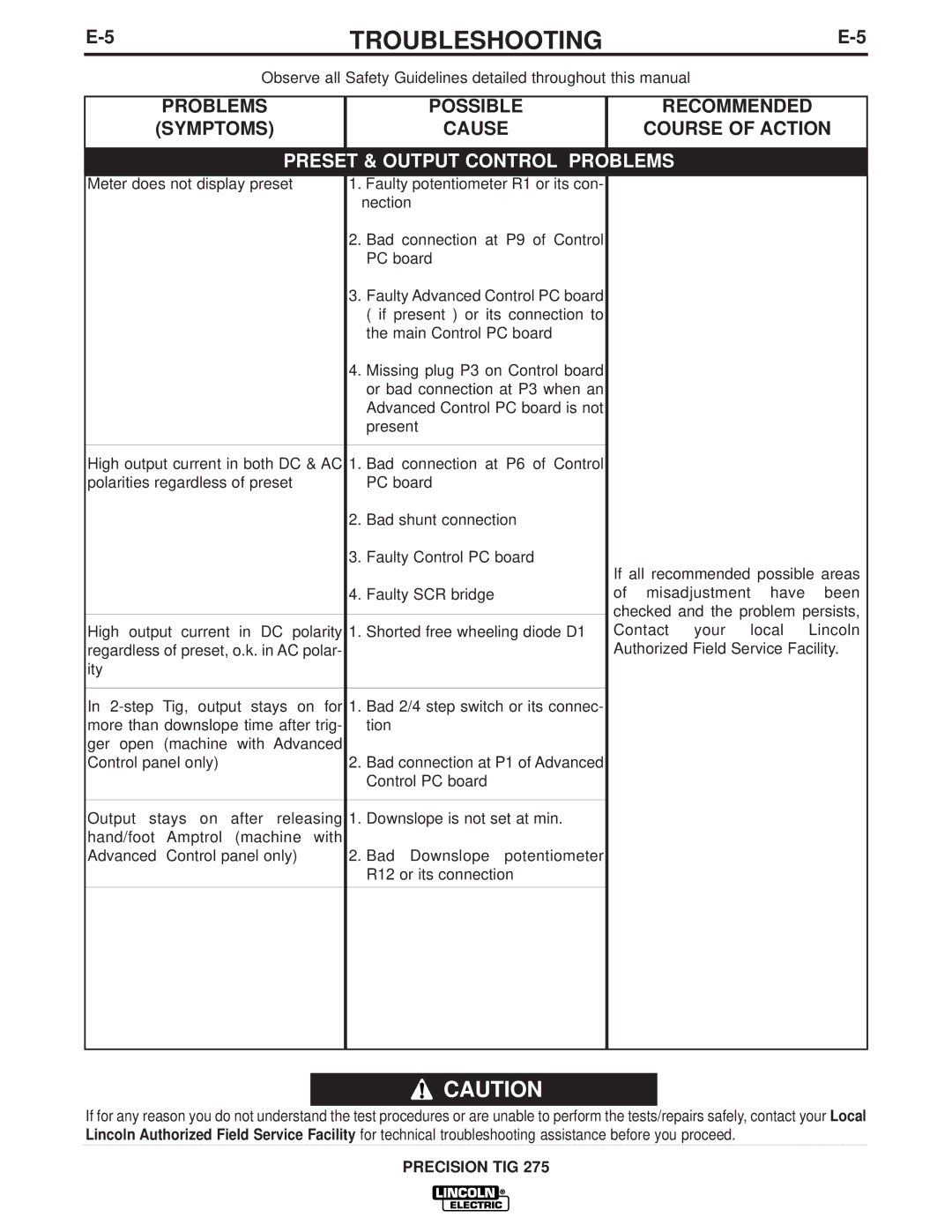
Lincoln Electric IM702-A manual Enhanced Diagrams

Page 40

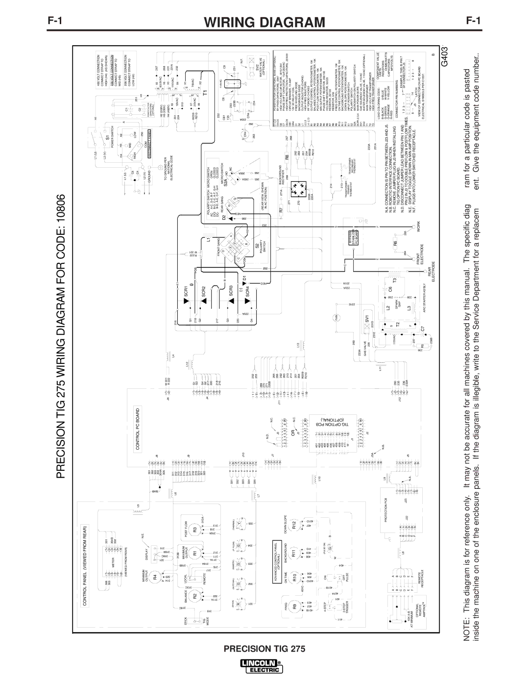
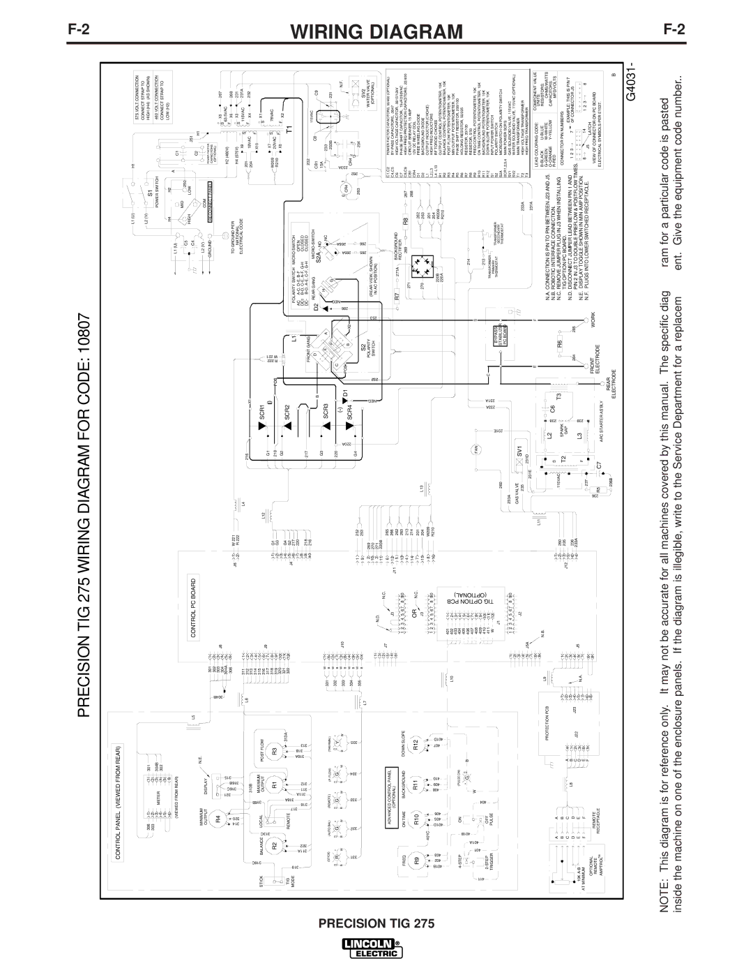
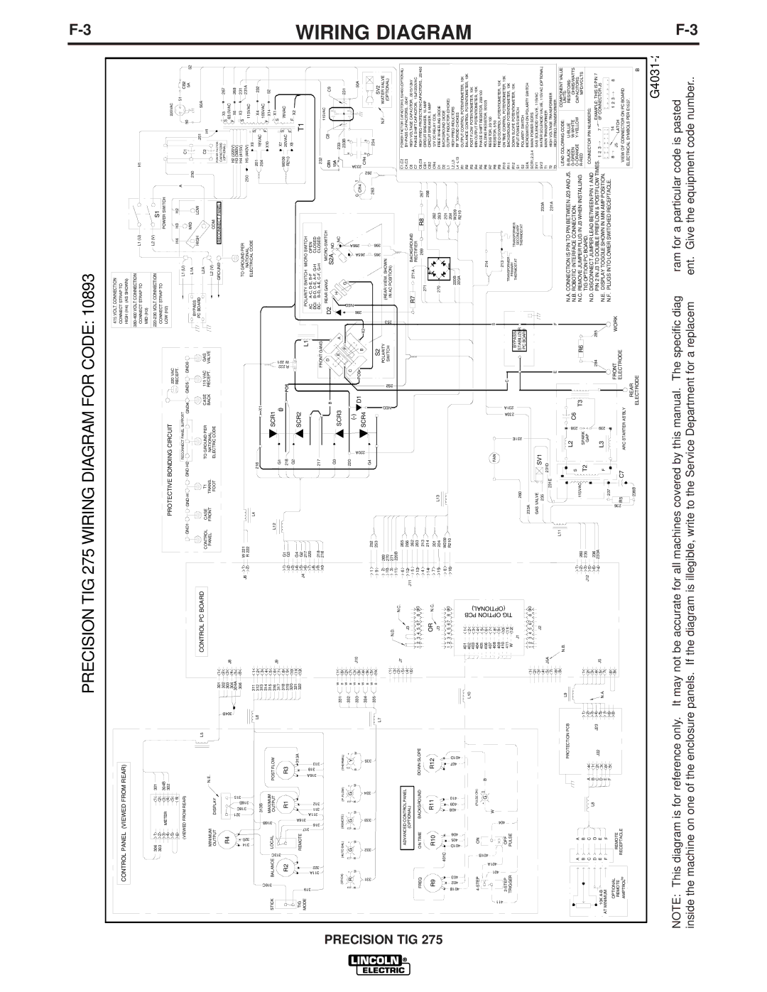
PRECISION TIG 275 WIRING DIAGRAM FOR CODE: 10893

F-3

CONTROL PANEL (VIEWED FROM REAR)

415 VOLT CONNECTION


CONNECT STRAP TO


HIGH (H4) (AS SHOWN)


380-400 VOLT CONNECTION

L1 (U)

H1

CONNECT STRAP TO

MID (H3)


306

1


1

301

303

2


2

304B


3

METER

3


4

4

302


5


5


6


6


(VIEWED FROM REAR)


L5

MINIMUM


N.E.

OUTPUT

DISPLAY


R4


301

1

304B

302

2

303

3

304

4

J8

CONTROL PC BOARD


220-230 VOLT CONNECTION

L2 (V)


S1


CONNECT STRAP TO


POWER SWITCH


PROTECTIVE BONDING CIRCUIT


LOW (H2)


220 VAC


220VAC


RECEPT.


H4

H3

H2

A


51


RECONNECT PANEL SUPPORT


L1 (U)


CB2


GND5

GND6


C1


50


GND1


GND-H

GND-H2

GND4


L1A


MID


5A

52


250


BYPASS

HIGH


LOW


PC BOARD


251

50A


CONTROL

CASE

T1

TO GROUND PER

CASE

115 VAC

GAS

L2A


C2


H1


PANEL

FRONT

TRANS.

NATIONAL

BACK

RECEPT.

VALVE

L2 (V)


COM


FOOT

ELECTRIC CODE


POWER FACTOR


GROUND

RECONNECT PANEL


CAPACITORS


S X5

267


(OPTIONAL)


H2 (220V)


63.5VAC


F


STICK

TIG

MODE

316C

319

BALANCE

R2


311A

322

313C

314

320


321

316C

316B

315


316B


313B


LOCAL


MAXIMUM


OUTPUT


R1


317

316

316A

311A

311

312


REMOTE


POST FLOW

R3


313A

316A

318

313


304A

5


306

6

L6

311

1

312

2


313

3


314

4


315

5


316

6


317

7


318

8


319

9


320

10


321

11


322

12


W

1


331


J9


H3 (380V)


X6

268

J6

1

W 221


TO GROUND PER


H4 (415V)


S

X3

231

2

R 222


NATIONAL

250

H5 (440V)


115VAC

231A


L4


ELECTRICAL CODE


201

X9

S


216

X1


18VAC


X4

232


204

F


105VAC


X10

F


X14

52


L12


SCR1


G1

R222 W221


X7


S

X1


1

G1

(+)


W209

S


78VAC


218

POS


20VAC


2

G3


R210

X8

F

F


3


G2


X2


G4


4


SCR2


T1


J4

5

G2


L1


POLARITY SWITCH MICRO SWITCH


6

217


7

220


AC

A-C, D-E, B-F

OPEN


8

218


DC+

B-D, C-E, A-F, G-H

CLOSED


9

217


FRONT GANG


DC- B-D, A-E, C-F, G-H

CLOSED


232


10

216


MICRO-SWITCH


115VAC


D


D2 REAR GANG


B


CB1

C8


C9


G3


S2A NO


15A


SCR3

E

A


H

NC


233


WIRING

(STICK)


(AUTO BAL)

(REMOTE)

(P. FLOW)


(THERMAL)


+ R -

+ G -

+ G -

+ G -

+

Y

-

B

W

B

W

B

W

B

W

B


W

331


332


333

334


335


ADVANCED CONTROL PANEL


(OPTIONAL)


FREQ


ON TIME


BACKGROUND


DOWN SLOPE


B

6

332

W

2

B

7


333

W

3

B

8


334

W

4

B

9


335

W

5

B

10

L7


1


3


2


5


4


6

J10

J7

N.D.

N.C.

J3

1 2 3 4 5 6 7 8 9 10


220


F


NEG


G


233B

231


)-(


C


266A


4

8


233ACR4


220A


286


265A

0 CR4 1


50A


D1


POS


SCR4


B

X2


2

6


1

252

G4


265

266

263

262


234


9

253


S2


SV2


2

269


NEG


POLARITY


253


(REAR VIEW, SHOWN


N.F.

WATER VALVE


10

270


252

SWITCH


(OPTIONAL)


IN AC POSITION)


3

271


11

220B


6

265


C1,C2


POWER FACTOR CAPACITORS, 50/460 (OPTIONAL)

J11

12

266


C4,C5


BY-PASS CAPACITORS, .0047

5

262


R7

271A

BACKGROUND


C6


HIGH VOLTAGE CAPACITOR, .0015/12kV


13

263


RECTIFIER


C7


PHASE SHIFT CAPACITOR, 15uF/250VAC


269

R8

267

C8,C9


HIGH FREQ PROTECTION CAPACITORS, .22/400


4

213


271


DIAGRAM

PRECISION TIG 275


R9


R10

R11


R12


401C


401B

402

403


401D

405

406

408

409

410


407

401D


L10


4-STEP

401A

401B

ON


404

(PULSE ON)


411


401


-

G +

B


W


2-STEP


OFF


TRIGGER


PULSE


1


2


3


4


5 J5A


7


6


8


PROTECTION PCB


L9


A


A


B


B


1


1


C


C


L8


A

4


2


2


D


D


B

1


J23

3


3


C

2

J22

4


4

J5


E


E


10K A-B


D

3


5

N.A.

5

AT MINIMUM


F


F


E

6


7


7


OPTIONAL


F

5


6


6


REMOTE


8


8


REMOTE


TM


RECEPTACLE


AMPTROL


OR N.C.

J3

1 2 3 4 5 6 7 8 9 10

401

1

OPTIONTIG PCB (OPTIONAL)

402

2

403

3

W

12

404

4


405

5


406

6


407

7


408

8


409

9


410

10


411

11


J1


1 2 3 4 5 6 7 8 9 10

J2

N.B.


14

214


268

CB1

CIRCUIT BREAKER, 15 AMP


CB2

CIRCUIT BREAKER, 5 AMP


7

201


L13


270


262

CR4

12V DC RELAY COIL


15

204


263

D1

FREE WHEELING DIODE


8

W209


201

D2

BACKGROUND DIODE


16

R210


204

L1

OUTPUT INDUCTOR (CHOKE)


220B


L2,L3

HIGH FREQ INDUCTORS


W209


L4 -L13

RF TOROID CHOKES


220A


R210


R1

OUTPUT CONTROL POTENTIOMETER, 10K


R2

BALANCE CONTROL POTENTIOMETER, 10K


R3

POST FLOW POTENTIOMETER, 10K


R4

MIN OUTPUT POTENTIOMETER, 10K


R5

PHASE SHIFT RESISTOR, 200/100


214


R6

HOLDING RESISTOR, 50/225


FAN


S


R7

RESISTOR, 20/100


R8

RESISTOR, 5/50


213


R9

FREQ CONTROL POTENTIOMETER, 10K


233A

231A

C


R10

ON TIME CONTROL POTENTIOMETER, 10K


TRANSFORMER


R11

BACKGROUND POTENTIOMETER, 10K


231E


BYPASS/

PRIMARY

TRANSFORMER


R12

DOWN SLOPE POTENTIOMETER, 10K


THERMOSTAT


260


STABILIZER


SECONDARY


S1

INPUT POWER SWITCH


THERMOSTAT


S2

POLARITY SWITCH


PC BOARD


233A


S2A

MICROSWITCH ON POLARITY SWITCH


GAS VALVE


SCR1,2,3,4

MAIN POWER SCR’S


SV1


SV1

GAS SOLENOID VALVE, 115VAC


235


233A

SV2

WATER SOLENOID VALVE, 115VAC (OPTIONAL)


231D


T1

MAIN TRANSFORMER


231E


E

F


231A

T2

HIGH VOLTAGE TRANSFORMER


L11


T3

HIGH FREQ TRANSFORMER


LEAD COLORING CODE:

COMPONENT VALUE


UNITS:


L2

238

C6


N.A. CONNECTION IS PIN TO PIN BETWEEN J23 AND J5.

B-BLACK


U-BLUE

RESISTORS:


1


S


N.B. ROBOTIC INTERFACE CONNECTION.


G-GREEN


W-WHITE

OHMS/WATTS


260


115VAC


T3

R6

N.C. REMOVE JUMPER PLUG IN J3 WHEN INSTALLING

O-ORANGE

Y-YELLOW

CAPACITORS:


2


T2

SPARK


R-RED


MFD/VOLTS


J12

3

235


GAP


TIG OPTION PC BOARD.


CONNECTOR PIN NUMBERS:


5


N.D. DISCONNECT JUMPER LEAD BETWEEN PIN 1 AND


236


6


284

285


EXAMPLE: THIS IS PIN 7


4

233A


PIN 2 IN J3 TO DOUBLE PREFLOW & POSTFLOW TIMES.

1 2 3


F

L3

239


N.E. DISPLAY TOGGLE SHOWN IN MIN AMP POSITION.

7 0F CONNECTOR J5


237


FRONT


N.F. PLUGS INTO LOWER SWITCHED RECEPTACLE.

8


14

1 2 3

8


236


WORK


J5


LATCH


R5

C7


ELECTRODE


ARC STARTER AS’BLY


VIEW OF CONNECTOR ON PC BOARD


REAR


ELECTRICAL SYMBOLS PER E1537.


236B


ELECTRODE


B


ENHANCED DIAGRAMS

G4031-2

NOTE: This diagram is for reference only. It may not be accurate for all machines covered by this manual. The specific diagram for a particular code is pasted inside the machine on one of the enclosure panels. If the diagram is illegible, write to the Service Department for a replacement. Give the equipment code number..

F-3

Image 40
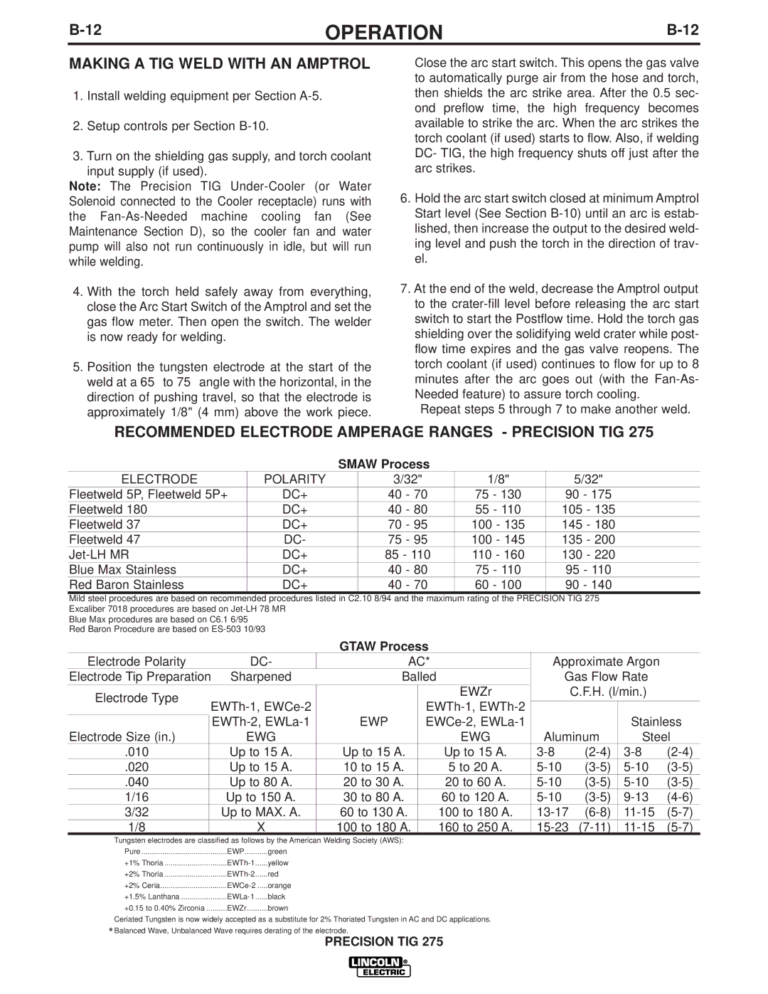
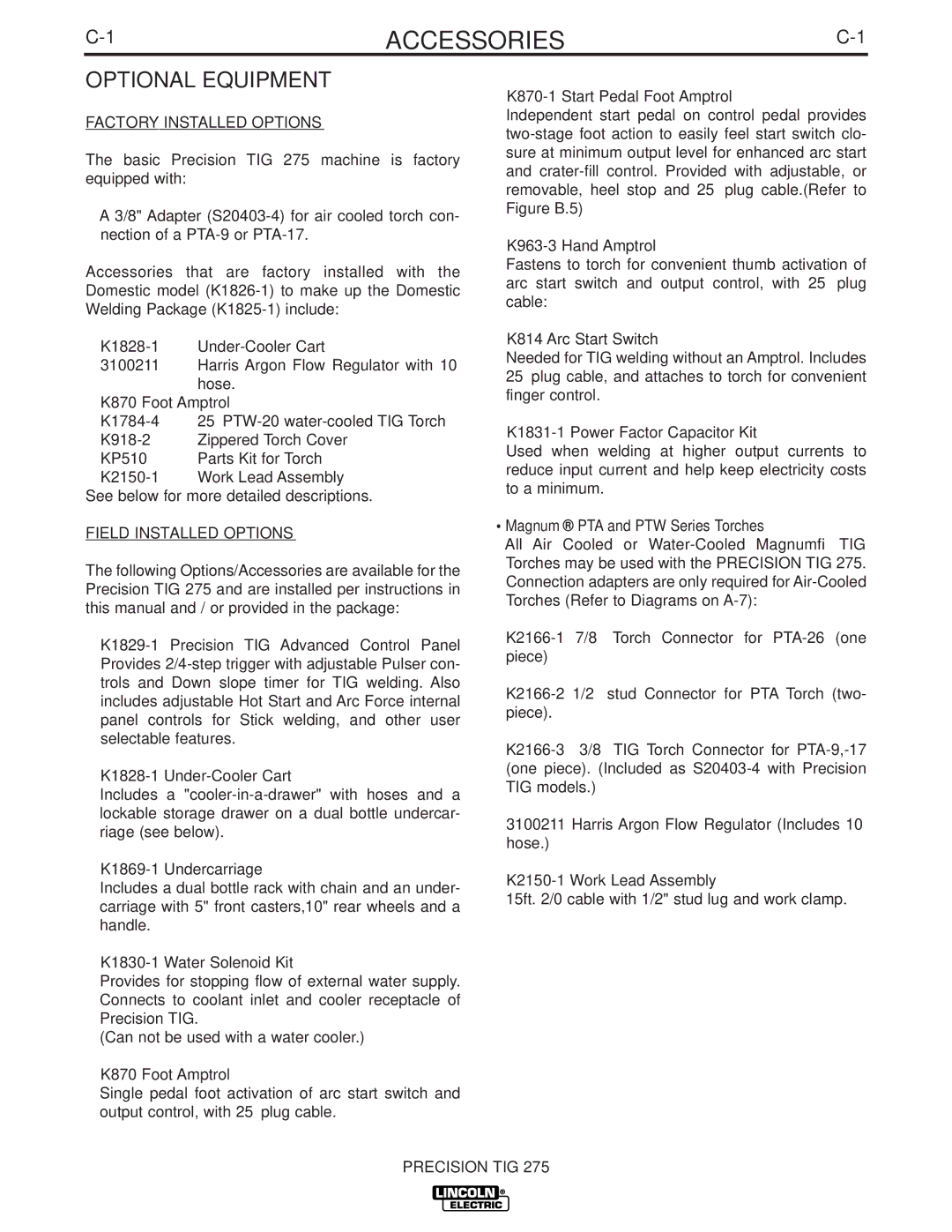
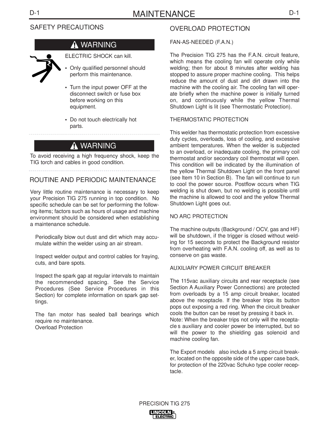
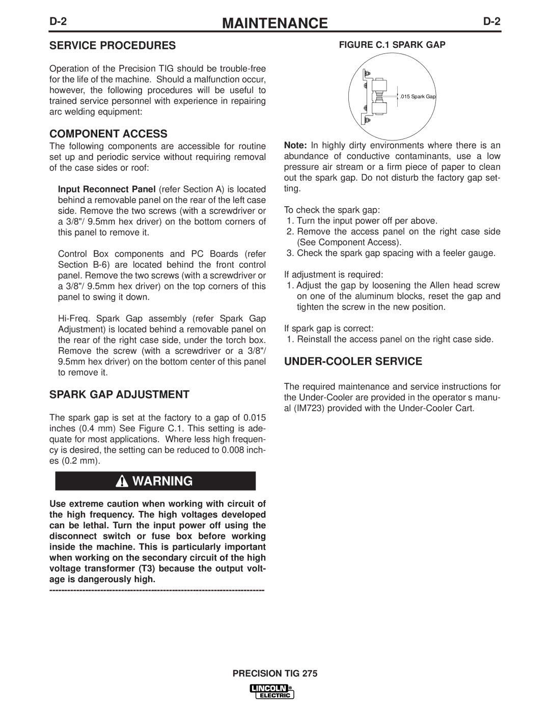
Contents Precision TIG Safety California Proposition 65 WarningsElectric Shock can kill Cylinder may explode if damaged Précautions DE Sûreté Sûreté Pour Soudage a L’ArcThank You Table of Contents Rated Input Single Phase only InstallationPrecision TIG Recommended Input Wire and Fuse Sizes Physical DimensionsTemperature Ranges Additional Output CapacitySafety Precautions Input and Grounding Connections Stick Electrode Cable Connection Work Cable ConnectionOutput CABLES, Connections and Limitations TIG Torch Connection Figure A.2Auxiliary Power Connections Figure A.3Robotic Interface Connection Figure A.4Operation Product DescriptionPipe Thawing Welding SparksRecommended Processes and Equipment Recommended ProcessesProcess Limitations Equipment LimitationsControls and Settings Figure B.1 Control PanelOperation Do not USE 4-STEP if Using AN Amptrol Remote Advanced Panel ControlsOperation Stick Welding Features Internal SET UP ControlsTIG Welding Features Figure B.3 Figure B.4 Setup Guidelines for TIG Welding with AN Amptrol TIG Weld Cycle ChartUsing the Start Pedal Foot Amptrol K870-1 Figure B.5 Making a TIG Weld with AN Amptrol Recommended Electrode Amperage Ranges Precision TIGAccessories Factory Installed OptionsField Installed Options Optional EquipmentMaintenance Safety PrecautionsRoutine and Periodic Maintenance Overload ProtectionService Procedures Component AccessSpark GAP Adjustment UNDER-COOLER ServiceTroubleshooting HOW to USE Troubleshooting GuideOutput Problems SymptomsCourse of Action Meter Problems GAS ProblemsHI-FREQ Problems Preset & Output Control Problems Stick Welding Problems TIG Welding ProblemsTIG Problems Precision TIG 275 Wiring Diagram for Code SCR3 Enhanced Diagrams Dimension Print K1826-1 DOMESTIC, K1826-2 Canada and K1827-1 Export Precision TIG Warnung Aviso DE

IM702-A specifications

The Lincoln Electric IM702-A is a versatile and innovative welding machine that has garnered attention for its advanced features and robust performance. Designed for various welding applications, the IM702-A is a go-to choice for professionals in the industry, offering precision, reliability, and ease of use.

One of the standout characteristics of the IM702-A is its advanced inverter technology. This allows for a lightweight and compact design, making it easier to maneuver in tight spaces compared to traditional welding machines. The inverter technology also contributes to energy efficiency, reducing power consumption without compromising on performance.

The IM702-A features a multi-process capability, enabling it to perform MIG, TIG, and Stick welding with ease. This versatility makes it ideal for a wide range of projects, from industrial manufacturing to home repairs. Users can seamlessly switch between different welding processes, enhancing productivity and streamlining workflow.

In terms of user interface, the Lincoln Electric IM702-A is designed with convenience in mind. It boasts a digital display that provides real-time information on welding parameters, making it easier for operators to monitor and adjust settings as needed. The intuitive controls are user-friendly, allowing even novice welders to achieve professional-quality results.

The machine also includes advanced weld control features, such as precise amperage and voltage adjustments. These controls ensure that users can achieve optimal settings for different materials and thicknesses, resulting in clean, strong welds. Additionally, the IM702-A is equipped with an automatic voltage adjustment feature, which helps maintain consistent performance under varying input conditions.

Durability is another key selling point for the IM702-A. Built with high-quality materials and engineering, this welding machine is designed to withstand the rigors of daily use in demanding environments. Its rugged construction provides reliability and longevity, ensuring that it remains a valuable asset in any workshop.

Lastly, safety is a priority in the design of the IM702-A. It includes several built-in safety features, such as thermal overload protection and a stabilized arc performance that reduces the risk of arc blow, protecting both the operator and the equipment.

Overall, the Lincoln Electric IM702-A stands out in the welding market due to its advanced technologies, multi-process capabilities, user-friendly interface, and robust safety features, making it an excellent choice for professional welders seeking high-quality performance and versatility.